Machine Learning in Civil Engineering - Advanced Surrogate Models with Graph Neural Networks
![[object Object]](/_next/image?url=%2Fimages%2Fauthors%2Fehsan_eshaghi.jpg&w=256&q=75)

Welcome to our third tutorial in this Machine Learning in Civil Engineering series. This one is going to step things up a notch as Ehsan introduces us to the world of neural networks.
Although these are not a completely new concept to me, I still find it a challenge to fully grasp how they work! But there’s no denying their power and utility.
If, like me, you’re somewhat of a novice in the world of machine learning, be prepared to do a little parallel reading as you work through this tutorial. It’s going to be a mental workout and you may want to research various terms that you encounter as you work through the tutorial.
The value here, from the engineer’s perspective, is seeing how these numerical tools and techniques can be applied to engineering analysis.
Even if you don’t grasp everything, on your first read-through - you should have a couple of lightbulb moments as you recognise the potential these models have when applied to our world of typically deterministic analysis.
📂 To follow along, make sure to download the Jupyter Notebook (linked above) to run locally as you read through the tutorial.
Ok, enough from me, enjoy!

In our previous tutorial, we designed a surrogate model to predict the deflection of truss elements under load without solving the system of equations. We achieved this by generating labelled samples and attempting to extract the relationship between two variables, and , using both a linear and then a non-linear function.
Subsequently, we reformulated our problem as a classification problem and observed that both regression and classification can be viewed as subcategories of a general machine learning framework called supervised learning.
We concluded that designing a surrogate model often involves solving a supervised learning problem. This is particularly useful when the exact mathematical model simulating the system's behaviour is computationally expensive.
In such cases, we seek a simpler function that can approximately predict the simulation output using a few labelled samples generated by our expensive simulator.
Essentially, we aim to find a computationally efficient function that, based on a few labeled samples from the expensive simulator, identifies a pattern between independent/explanatory variables and one or more dependent variables. This function should generalise to unseen inputs, predicting the system's behaviour for designs that were not simulated.
1.0 Problem Statement
Now let’s build on what we learned previously and explore a more realistic yet simplified 2D problem. Our task is to assess the stability of a frame structure under the following conditions:
Loading:
- Lateral Load: Point load on each level representing wind from left to right, increasing with height.
- Vertical Load: SDL, uniform (300 KN/m)
Stability Criteria:
- Lateral drift:
- Vertical deflection:
Modulus of Elasticity (MOE):
- 32800 MPa
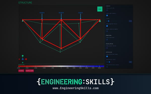
In the following sample image, beams and columns that do not meet the stability criteria are coloured red; we call these invalid elements. The blue elements are considered valid. A structure is valid only if all its elements are valid (i.e., the deflection of beams and drift of columns are within the specified thresholds).
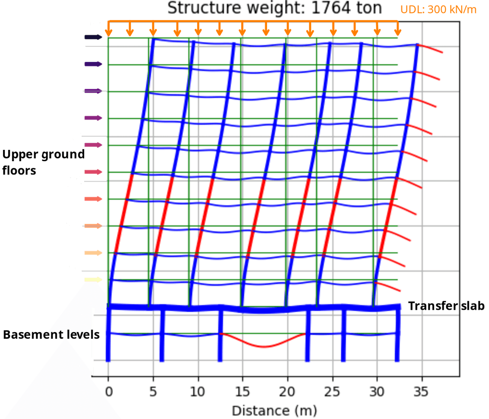
Fig 1. Sample frame showing valid frame elements in blue and invalid elements in red.
1.1 Features of the problem
This problem differs from our previous truss deflection prediction in several ways:
-
Frame Elements vs. Truss Elements: Unlike axially loaded truss elements, we are using frame elements. Changing the element type from truss to frame modifies our stiffness matrix. We still need an efficient function (a surrogate model) to estimate the displacement vector using the stiffness matrix and force vector .
-
Validation Threshold: Instead of estimating the deformation itself, we assess whether the deformation satisfies a valid threshold (maximum normal deflection for beams and maximum drift for columns). Structural engineers generally do not focus on the exact deformation value as long as it is within the specified limit.
Additionally, fitting a classifier that only has to predict whether the deformation is valid or not can sometimes be easier. You can read more about classification vs. regression in this tutorial.
-
Multiple Elements: We aim to predict the behaviour of all elements in the structure under load. A structure is valid if all its elements are valid. Hence, we need to estimate multiple outputs (one for each element) for a structure with elements.
-
Multiple Loads: The structure is subjected to multiple vertical and lateral load forces.
-
Generalised Function: Our objective is to create a function that can estimate the deflection for any frame structure with arbitrary geometry (arbitrary stiffness matrix) and under arbitrary load vectors. However, the diversity of possible structures that can be modelled with frame elements is vast, and the relationship between design variables and deformation can be highly complex in the general case.
Capturing this diversity and designing a function that accurately approximates the deflection of any structure would require generating billions of samples for various frame designs and loads to extract meaningful patterns. This task is beyond the scope of this tutorial.
Therefore, we will focus on a family of frame structures with specific constraints on their geometrical arrangement and loading. Our goal is to analyse the stability of grid layout frame structures where the first two levels have the same slab plan and column layout, which differs from the slab plan of the upper levels.
In other words, the grid layout is consistent within the two lower levels and within all the upper levels, but not necessarily between them. These designs resemble a simplified version of a concrete frame building with two basement levels (e.g. for parking) and an arbitrary number of above-ground residential levels. Therefore, the first-floor beams are typically transfer beams.
We have limited our samples to a maximum of 11 above-ground levels. The pattern of lateral and vertical loads is depicted in the image: the lateral load increases with height and is only applied to the above-ground levels, while the vertical load is uniformly distributed () on each level.
To focus on surrogate model design rather than sample generation, I have pre-generated 1000 samples, stored using a graph data structure, which you will learn about later.
2.0 Graph Representation of the Structure
Our work is supported by our members. Please consider supporting our original (human!) content creation by subscribing to our membership.
All Access Membership
Learn, revise or refresh your knowledge and master engineering analysis and design

Access Every Course and Tool
- Over 1140 lectures & over 234 hours of HD video content
- Access member-only 'deep dive' tutorials
- Access all downloads, pdf guides & Python codes
- Access to the StructureWorks Blender addon + updates
- Packed development roadmap of courses & tutorials
- Price Guarantee – avoid future price rises as we grow
- Priority Q&A support
- Course completion certificates
- Early access to new courses
Featured Tutorials and Guides
If you found this tutorial helpful, you might enjoy some of these other tutorials.
Building Custom Engineering Tools in Python with PyQt
A step-by-step guide to designing workflow-first engineering tools that interface with your FE software

Hakan Keskin

Building a Mohr’s Circle Calculator for Stress Analysis in Python
Once complete, you will have your own stress analysis Python code

Dr Seán Carroll