A Complete Guide to the Flexibility Method for Beam and Frame Analysis
![[object Object]](/_next/image?url=%2Fimages%2Fauthors%2Fjulian_haudek.jpg&w=256&q=75)
Welcome to another in-depth engineering tutorial. In this one, Julian Haudek takes us through a structural analysis classic, the Flexibility Method. Often considered the stiffness method’s ugly sister (at least if you’re a programmer), it’s nevertheless a really powerful and elegant analysis technique - ideally suited to indeterminate structures with relatively low levels of indeterminacy.
This is a really in-depth presentation - building from the fundamental theory up to the analysis of statically indeterminate frames. Give yourself plenty of time to work through and digest it - especially if you’re hitting this topic for the first time.
The tutorial breaks down as follows:
1.0 Statically Indeterminate Structures
The flexibility method relies on initially identifying redundancies in the structure. So naturally, a very clear understanding of statically determinacy is key. We start with a brief review to make sure we’re on solid ground before moving forward.
2.0 The Flexibility (Force) Method – Concept
Then, we move on to break down the core concept behind the flexibility method. Understanding the step-by-step analysis procedure is obviously important - but it all makes so much more sense when you understand fundamentally why each step is performed. Section 2 does a good job of covering both theory and implementation.
3.0 When to Use the Flexibility Method
The flexibility and stiffness methods are often referenced together. In section 3, we briefly discuss the similarities and differences between these two analysis techniques and when one should be favoured over the other.
4. Example I - Statically indeterminate beam
With all of the theory covered, the only thing left to do is see it in action. As usual, no tutorial is complete without a good worked example to tie everything together. In section 4 we start of gently with a simple indeterminate beam analysis.
5. Example II - Statically indeterminate moment frame
We finish up with the analysis of a statically indeterminate frame. This allows us to stretch ourselves with something a little more involved than the beam we analysed in the previous section.
I hope you enjoy the tutorial and find it helpful - now over to Julian!

1.0 Statically Indeterminate Structures
Understanding the concept of determinancy and specifically the degree of static indeterminacy of a given structure is going to be central to our understanding of the Flexibility Method and how to apply it. So, let's start our exploration of the flexibility method with a brief recap of static determinacy.
What's the difference between the two beams in Fig 1. below? Before diving into the Flexibility Method, let's start with this simple but fundamental question.

Fig 1. Beam with pin-roller restraint (left) and pin-pin restraint (right).
At first glance, both beams may look similar, but the key difference lies in their static determinacy. One is statically determinate, meaning any first-year engineering student can solve it using just the equilibrium equations. The other, however, is statically indeterminate, and that's where things get tricky - equilibrium alone isn't enough, and we need additional compatibility equations to find the unknowns. This brings us to the main topic: statical indeterminacy and how to handle it using the Flexibility Method.
A statically indeterminate structure (also called a hyperstatic structure) is a geometrically stable system where the internal forces and reactions cannot be determined using only the three equations of static equilibrium. This is in contrast to statically determinate systems, where the number of unknowns matches the number of equilibrium equations, making direct calculations possible.
Key Characteristics of Statically Indeterminate Structures:
- More constraints (supports or internal connections) than needed for geometric stability.
- Internal forces depend on stiffness properties (material and geometric characteristics of the members), unlike determinate structures where forces depend only on equilibrium.
- They can develop internal stresses even in the absence of external loads due to effects like temperature changes, foundation settlements, etc.
- There are infinitely many possible solutions that satisfy equilibrium conditions, but only one that also satisfies compatibility and material behaviour.
1.1 Degree of Static Indeterminacy (DSI)
The degree of static indeterminacy (DSI) represents the number of additional equations required (beyond equilibrium equations) to fully determine all internal forces and reactions in a structure. There are different ways to determine the degree of static indeterminacy (DSI) depending on the type of structure. The most common formulas are:
For open frames and beams:
where:
- = number of reactions,
- = number of equilibrium equations,
- = number of hinges.
For trusses, a more practical equation is:
where:
- = number of unknown internal forces (axial forces in truss members),
- = number of unknown reaction forces from supports,
- = number of joints (nodes).
1.2 Example I
Let's go back to the beam we introduced earlier. At first glance, it seemed like a straightforward structure, but now that we understand static indeterminacy, let's formally determine its DSI.
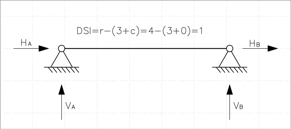
Fig 2. Pinned-pinned beam with degree of indeterminacy calculated.
The beam is supported at two points:
- Pinned support A providing two reactions: (horizontal) and (vertical).
- Pinned support B providing two reactions: (horizontal) and (vertical).
This gives us a total of:
Since there are no internal hinges, the number of additional internal constraints is:
Using the DSI formula for beams and frames:
For this beam, substituting the values:
This confirms that the degree of static indeterminacy (DSI) of our beam = 1.
1.3 Example II
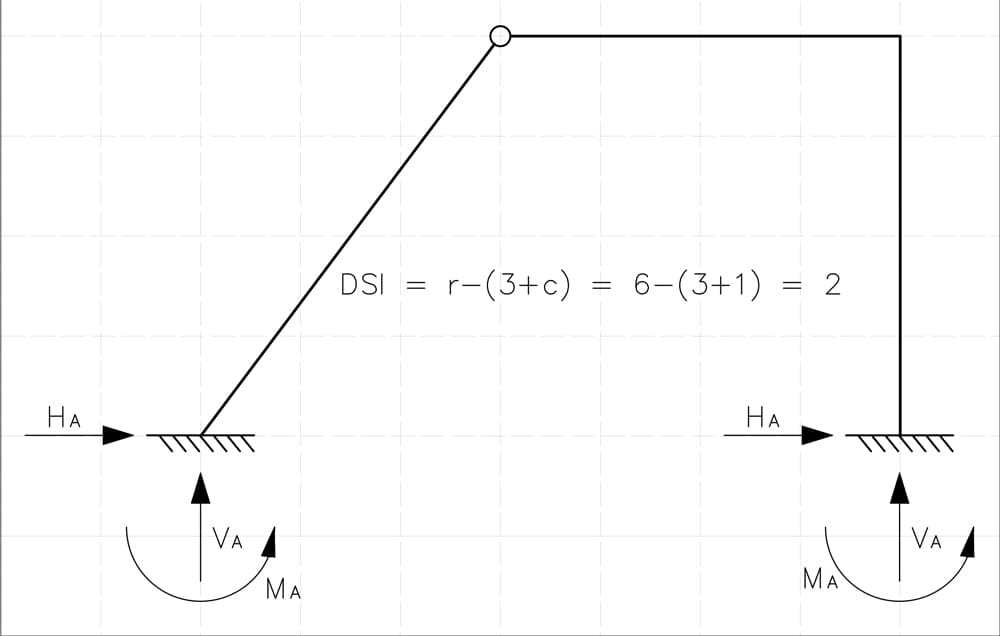
Fig 3. Frame with two fixed supports and an internal hinge.
The given frame is supported at two fixed supports, each providing three reaction components: a horizontal force, a vertical force, and a moment reaction.
This results in a total of:
- reaction forces.
Additionally, the frame contains one internal hinge, contributing an extra equation of equilibrium.
Applying the DSI formula:
Substituting the values for this structure:
Thus, the degree of static indeterminacy (DSI) of this frame is 2.
1.4 Example III
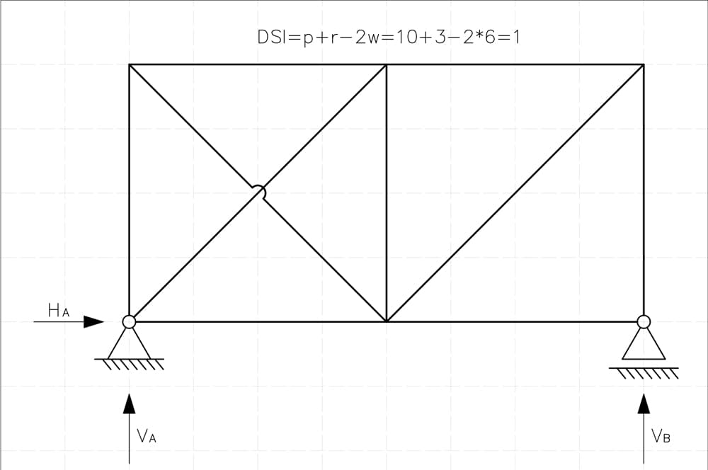
Fig 4. Truss with pin and roller support.
This truss is supported at two points:
- Pinned support at A providing two reactions: (horizontal) and (vertical).
- Roller support at B providing one reaction: (vertical).
This results in a total of:
- r = 3 external reaction forces.
- p = 10 internal forces (number of truss members).
- w = 6 joints (nodes).
Applying the standard formula for trusses:
Substituting the values:
This confirms that the degree of static indeterminacy (DSI) of this truss is 1.
Now that we've refreshed our understanding of static indeterminacy, let's move on and start digging into the Flexibility Method.
2.0 The Flexibility (Force) Method – Concept
The Flexibility Method, also called the Force Method is one of the classical approaches to analyse statically indeterminate (hyperstatic) structures. In this method, the primary unknowns are the redundant forces (or moments), and the solution relies on enforcing compatibility of displacements in those directions where additional constraints (beyond what is needed for static determinacy) exist. Initially, this sounds quite abstract, so let’s review the theoretical foundations and the typical steps involved in an analysis.
As we already know, a statically indeterminate (hyperstatic) structure has more unknown internal forces and reactions than can be determined from the equilibrium equations alone. To solve this problem we must add compatibility conditions to account for the fact that certain deformations (displacements, rotations) are constrained by the extra supports or internal connections.
The Flexibility Method systematically converts the original hyperstatic structure into a statically determinate one by virtually removing the “extra” constraints (the ones creating indeterminacy) and replacing them with unknown redundant forces or redundant moments.
We then write down additional equations - compatibility equations - to ensure that the resulting displacements in those freed directions remain exactly as they would in the real, fully constrained structure (i.e., typically zero displacement or zero relative displacement across a cut).
2.1 The Flexibility Method - Analysis Steps
Step 1: Determine the Degree of Static Indeterminacy (DSI)
As we already know, DSI is the number of redundant forces (or moments) needed to convert the hyperstatic structure into a determinate one. In this tutorial, we will focus on frames and beams so we will be using the following formula, discussed above:
Step 2: Identifying Redundant Constraints and Creating the Primary System
Our next step is to identify and remove redundant constraints to reduce the structure's DSI denoted as . These redundant constraints can be found among external supports or internal constraints (e.g., internal member connections in trusses or frames).
The removal process must ensure that the resulting system remains geometrically stable to avoid forming a mechanism and, ideally, statically determinate to simplify further analysis. While the primary system does not strictly need to be statically determinate, choosing an indeterminate one would only introduce unnecessary complexity.
By eliminating these redundant constraints, we obtain a primary system, which serves as the foundation for further analysis. This statically determinate model allows us to set up compatibility equations, which ensure that the structure returns to its original state by accounting for the displacements caused by removing constraints. In other words, eliminating these constraints introduces movements that were previously restricted, and these additional equations are needed to properly control them and maintain equilibrium.
Step 3: Introducing the Hyperstatic Forces
At the points where constraints were removed, we introduce hyperstatic forces, to account for their effects. These forces, denoted as (for ), act as replacements for the removed constraints and will later be determined using compatibility equations.
The type of force introduced depends on the nature of the removed constraint. If a support that restricts translation was removed, we introduce a force at that location. If a support that restricts rotation was removed, we introduce a moment instead.
The ultimate goal of the Flexibility Method is to determine the values of these hyperstatic forces , treating them as additional external loads applied to the primary system.
Step 4: Displacement Analysis of the Primary System
Since we've established our statically determinate primary system, we can now evaluate the displacements at the locations where constraints were removed. These displacements naturally occur, as the structure - previously constrained - can now deform freely under both the actual external loads (state P) and the introduced hyperstatic forces.
The total displacement at the location of each removed constraint, denoted as , is thus composed of two distinct components:
- Displacement due to the introduced hyperstatic forces , which replace the removed constraints.
- Displacement caused exclusively by the actual external loading (state P).
Mathematically, this relationship is clearly expressed as:
where:
- – flexibility coefficient, representing the displacement at constraint caused by a unit value of the hyperstatic force at constraint .
- – displacement at constraint due solely to the external loads in the real loading state (state P).
If we have multiple hyperstatic forces, we obtain a clear system of equations, known as the compatibility conditions:
These compatibility equations ensure that the final structure’s deformation matches the actual, original statically indeterminate system. Solving this system allows us to determine all unknown hyperstatic forces , thus enabling us to reconstruct internal forces and reactions in our original structure.
Step 5: Impose Equilibrium in the Primary System
Now that we have the primary system, solving it is straightforward since it is statically determinate. We can use standard equilibrium equations (e.g., , ) to determine internal shear, bending moment, axial forces, and reactions under the actual external loads.
These internal force diagrams and reaction values represent the response of the structure to the real external loading after the redundant constraints have been removed.
Step 6: Setting Up Compatibility Equations
The core principle of the Flexibility Method is straightforward: after introducing the unknown redundant forces into our primary system, the resulting displacements at the locations of removed constraints must match exactly those of the original, fully constrained structure.
Typically, this simply means enforcing that these displacements equal zero - since, originally, the constraints prevented any displacement in those directions.
We define the total displacement at the location of the -th removed constraint as . As previously explained, this displacement has two clear components: one due to the actual external loads (state P), and one due to the introduced hyperstatic forces. Thus, we can express the general compatibility condition mathematically as:
where:
- is the displacement at the -th constraint location caused exclusively by the external loading (state P) applied to the primary system,
- is the flexibility coefficient, representing displacement at constraint due to a unit redundant force or moment applied at constraint .
Since the original structure was fully constrained, the compatibility conditions typically require that these total displacements are zero:
We can neatly write this system in compact matrix form commonly known as the flexibility matrix equation:
where:
- is the flexibility matrix, consisting of coefficients ,
- is the vector containing unknown redundant forces or moments,
- is the vector of displacements resulting solely from actual external loads (state P).
By solving this set of equations, we obtain the unknown redundant forces, thus enabling us to restore equilibrium in the original, statically indeterminate structure.
Step 7: Computing Flexibility Coefficients and Displacements
To determine the flexibility coefficients , we apply a unit load or unit moment at the location and direction of the -th redundant force on the primary system, keeping all other redundant forces set to zero. The displacement computed at the location of the -th redundant constraint is the corresponding flexibility coefficient .
Similarly, to find the displacement , we analyse the primary system subjected only to the real external loads (state P), without any redundant forces applied. These displacements and flexibility coefficients can be efficiently computed either by classical deflection formulas (such as direct integration of bending moment diagrams) or using the Principle of Virtual Work (Unit Load Method).
Step 8: Solving for the Redundant Forces
Once the system of compatibility equations is fully established, we solve for the unknown redundant forces . These values restore the original constraint effects in the structure while ensuring that compatibility conditions are satisfied.
Step 9: Recovering Internal Forces and Reactions
Once we've solved for the unknown redundant forces , we can restore the original statically indeterminate structure by reapplying these forces onto the primary system, using the principle of superposition. Consequently, the total internal forces, moments, and reactions in the real structure become simply the sum of two distinct states:
- The internal force response of the primary system due exclusively to the real external loads (state P).
- The internal force response of the primary system due to each individual hyperstatic force applied separately (unit states scaled by their computed magnitudes).
For example, the bending moment distribution in the original structure can be expressed as:
where:
- – the bending moment in the primary system caused solely by the real external loads (state P),
- – the bending moment in the primary system caused by a unit load (or moment) applied at the -th redundant location.
Similar expressions apply straightforwardly to shear forces, axial forces, and reactions. By following this structured approach, we efficiently reconstruct all internal force distributions and reactions, successfully completing our solution using the Flexibility Method.
3.0 When to Use the Flexibility Method
The Flexibility Method is particularly useful when dealing with structures that have a low degree of static indeterminacy, typically when the number of redundant forces is small ().
In such cases, the system of compatibility equations remains manageable, and solving for the unknown redundants does not become computationally overwhelming. This makes the method effective also for trusses with only one or two extra bars, where removing selected members results in a simple, determinate system without compromising stability.
When dealing with highly indeterminate structures - particularly complex frames with many redundants the flexibility method quickly becomes impractical. In such cases, the Stiffness (Displacement) Method is often a better choice, especially in modern computational contexts, where matrix-based numerical approaches are more efficient for large systems.
This is also why most structural analysis software relies primarily on the Stiffness Method, as it is easier to implement in code and better suited for automation.
Since we have mentioned the Stiffness Method as an alternative approach, here is a brief comparison between the two methods to highlight their key differences and typical applications.
Both the Flexibility (Force) Method and the Stiffness (Displacement) Method are fundamental approaches to solving statically indeterminate structures, but they differ significantly in methodology, application, and computational efficiency.
3.1 Flexibility Method vs. Stiffness Method - Conceptual Differences
The Flexibility Method treats redundant forces as unknowns and solves for them using compatibility equations, ensuring that displacements match those of the original constrained system. In contrast, the Stiffness Method treats nodal displacements as unknowns, formulating equilibrium equations based on force-deformation relationships.
The Flexibility Method is best suited for structures with few redundants because the number of unknowns (redundant forces) grows with the degree of static indeterminacy. The Stiffness Method, however, is more effective for highly indeterminate structures, as it scales better computationally, making it the preferred choice in structural analysis software.
We can conveniently summarise the key differences between the two methods in the table below:
| Flexibility Method (Force Method) | Stiffness Method (Displacement Method) | |
|---|---|---|
| Primary Unknowns | Redundant forces | Nodal displacements |
| Equations Used | Compatibility equations | Equilibrium equations |
| Main Matrix | Flexibility Matrix | Stiffness Matrix |
| Best for | Structures with few redundants | Highly indeterminate structures |
| Computational Feasibility | Tedious for large , requires flexibility coefficients | Efficient, suited for matrix computation |
| Common Applications | Hand calculations for frames, trusses | Hand calculations and software implementation |
3.2 Choosing the Right Method
Both the Flexibility Method and the Stiffness Method are powerful tools, and the choice between them depends not only on the structure itself but also on the experience and intuition of the engineer. The same frame or beam system may be straightforward using one method and overly complicated with the other.
A highly indeterminate frame may be difficult to handle with the Flexibility Method, requiring extensive calculations of flexibility coefficients, while the Stiffness Method might reduce the problem to a systematic matrix solution.
On the other hand, a simple beam with just one redundant might be solved in minutes using compatibility equations, whereas setting up and solving a stiffness matrix could be overkill.
Ultimately, selecting the right method comes down to understanding the problem, recognising which approach minimises effort, and leveraging experience to make the solution as efficient as possible.
3.3 Summary
The Flexibility Method (also known as the Force Method) simplifies the challenge of solving statically indeterminate structures by transforming a problem of unknown internal forces into a linear system involving displacements.
Instead of working directly with equilibrium conditions, we first remove redundant constraints, introduce unknown forces or moments at those locations, and then enforce compatibility equations to ensure that displacements remain consistent with the original structure's geometry.
The key idea is to exploit superposition, where the final solution is obtained by adding:
- The effects of the real external loads acting on the primary system (i.e., the reduced statically determinate structure).
- The effects of each redundant force acting alone on the primary system, scaled by its corresponding unknown magnitude.
This systematic approach explains why the method is sometimes called the Compatibility Method - the additional equations arise from the requirement that displacements at redundant constraint locations remain compatible with those in the original structure. Once the redundant forces are determined, the structure behaves like a statically determinate system, allowing internal forces and reactions to be found using standard equilibrium conditions.
4. Example I - Statically indeterminate beam
Now that we've covered the theory, it's time to put it to work. We now have all the tools we need to tackle real-world statically indeterminate structures using the Flexibility Method. To start off easy, let's take on a simple statically indeterminate beam, as shown in Fig 5. below.
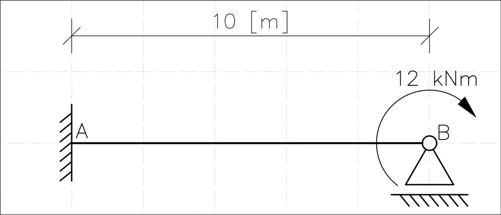
Fig 5. Statically indeterminate beam, fixed-roller supports.
We're dealing with a beam supported by a fixed support at A and a roller support at B, loaded with a 12 kNm nodal moment at B. Let's start and apply what we learned.
4.1 Degree of Static Indeterminacy (DSI)
First, we need to determine how statically indeterminate this beam actually is. The formula for the DSI is:
where:
- (number of reaction components: horizontal , vertical ), and moment at the fixed support, plus vertical reaction at the roller support),
- (no internal hinges).
Plugging in the values:
DSI = 1, our structure is singly statically indeterminate, which makes it a perfect candidate to calculate it using Flexibility Method.
There are many equally valid ways to do this, as shown in Fig 6. The choice depends on our engineering intuition - a well-chosen primary system makes the problem simple, while a bad choice makes it frustratingly laborious.
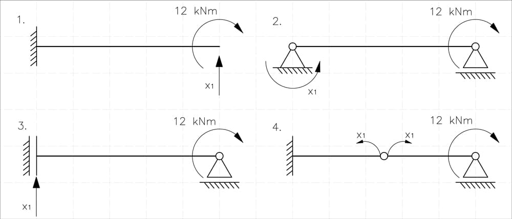
Fig 6. Four possible methods of achieving a statically determinate structure.
Among these, I choose Option 1 - removing the vertical reaction at B - because a cantilever beam is typically the easiest system to analyse. However, the other choices are equally valid. In fact, one could argue that a simply supported beam (as in Option 2) might even be simpler in certain cases - it's largely a matter of personal preference and experience.
A few key observations:
- We cannot remove the horizontal reaction at A - if we did, the structure would become a mechanism.
- Option 4 doesn’t actually remove a support - instead, it introduces an internal hinge, which is also a valid approach but often less convenient for calculations.
4.2 Solving the Primary System
Now that we have our statically determinate primary system, we need to analyse it in two separate loading conditions:
-
Effect of the external load – in our case, a moment applied at B. We will call this State P.
We don't need to do much calculation here, since we can use equilibrium conditions directly:
As there is no horizontal or vertical forces all we need to calculate is:
So we immediately get .
With this, we can easily draw the bending moment diagram for the beam in state P, Fig 7.
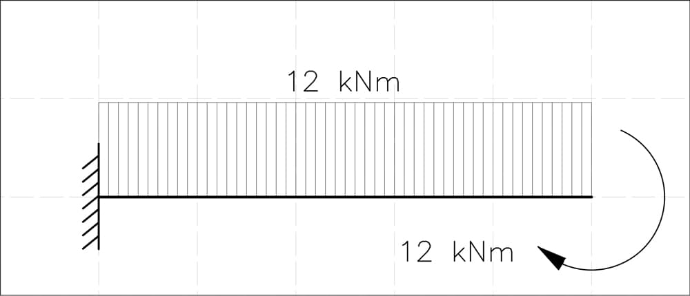
Fig 7. State P bending moment diagram showing the influence of the applied actions on the statically determinate system.
- Effect of a unit force at B in the direction of the removed reaction (remember that we don't have a unit here).
To analyse this case, we apply the unit load method, which means we introduce a hypothetical unit force at B and determine the corresponding response of the structure.
Again, we use the equilibrium equations:
So we get .
Evaluating the sum of the moments, ,
Which gives . With these values, we can now draw the bending moment diagram for this case.
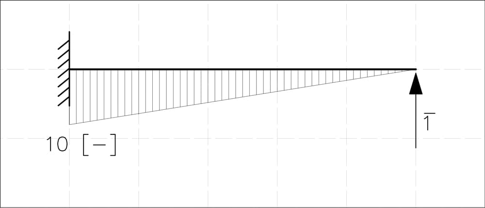
Fig 8. Bending moment diagram due to a unit load applied at the location and in the direction of the removed restraint.
4.3 Formulating the Compatibility Equation
Now that we have solved the primary system for both loading conditions, we can move on to the key step of the Flexibility Method - setting up the compatibility equation to determine the unknown redundant force .
Since we removed one redundant constraint, the structure must still satisfy the compatibility condition - the total displacement at the removed support must be zero.
To do this, we must combine the effects of the two separate states:
- State P – the displacement due to the external load.
- State 1 – the displacement due to a unit force applied at the removed support.
These two effects are related by the following canonical (compatibility) equation:
where:
- – the unknown redundant reaction we need to solve for.
- – the displacement at the removed support due to State 1 (unit force ).
- – the displacement at the removed support due to State P (external load).
To determine and , we use integration of bending moment equations.
Once we solve for , we can reconstruct the original indeterminate system, determining all reactions and internal forces.
4.4 Introduction to Vereshchagin's Integration Method
To compute the displacements and , we will use Vereshchagin’s graphical integration method, also known as the graph multiplication method. This method provides an efficient way to determine deflections and rotations by analysing the bending moment diagrams without requiring direct analytical integration. Instead of solving complex integrals, it transforms the problem into a simpler area-based approach, making it particularly useful for us.
Fundamental Equation
The general expression for displacement at a given point in a structure, derived from the principle of virtual work, is:
where:
- is the bending moment function due to State 1,
- is the bending moment function due to another state, in our case - State P,
- is the flexural rigidity of the beam, assumed constant.
Graphical Integration Using Vereshchagin’s Method
Instead of relying on complicated integral calculus, Vereshchagin’s graphical integration method allows us to simplify displacement calculations by using geometric properties of the bending moment diagrams directly. The integral equation:
can conveniently be expressed by the much simpler graphical relationship:
where:
- is the area under the first moment diagram
- is the corresponding ordinate (value) from the second moment diagram , evaluated at the centroid of the area .
This straightforward geometric interpretation significantly streamlines displacement calculations, eliminating the need for analytical integration and making structural analysis simpler and more intuitive.
Applying Vereshchagin’s Method in Practice
As a reminder, the governing equation for the Flexibility Method in our case is:
With everything in place, let’s move on to the calculations.
4.4.1 Computing – Displacement Due to Unit Force
To determine , we apply Vereshchagin’s integration method to our moment diagrams. In this case we have integration of two identical triangles. So our situation looks like this:
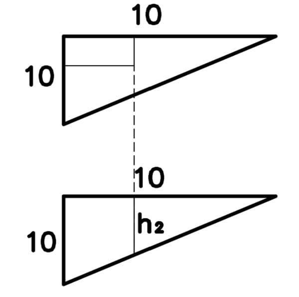
Fig 9. Vereshchagin’s integration method applied to two triangular portions of bending moment diagram.
Based on the diagrams shown above, we follow these steps:
- Calculate the area of the upper triangular moment diagram (from state 1).
- Locate the centroid of this area and identify the corresponding ordinate on the second moment diagram (also from state 1). For triangles, the centroid is always located at of the length measured from the triangle’s sharp vertex so we know that:
- Compute displacement by multiplying these two values and dividing by :
This straightforward graphical calculation replaces complex integral calculus with simple geometric operations, making the structural analysis clearer and faster.
4.4.2 Computing – Displacement Due to External Load
To compute , we again apply Vereshchagin’s integration method, this time integrating the triangular moment diagram (from State 1) with the rectangular moment diagram (from State P).
This time the process is:
-
Calculate the area of the triangle from the first moment diagram (unit load state):
-
Locate the centroid of this triangular area. For triangles, the centroid is always located at from the triangle’s sharp vertex. Thus, the centroid position is:
At this centroid location, we identify the corresponding ordinate on the second moment diagram (from the external load state), which is rectangular with height everywhere. Therefore:
- Compute displacement by multiplying the area by the ordinate , then dividing by :
4.5 Solving the Compatibility Equation for the Redundant Force
Having computed both necessary displacement values, we can now solve the compatibility equation to determine our unknown redundant force . Compatibility equation for our system is:
We already computed these values:
Substituting these results into our compatibility equation, we obtain:
Now, let's solve for our unknown redundant force :
Multiply both sides by :
Solve for the unknown redundant reaction :
Now that we have the value of the redundant reaction:
4.6 Reconstructing the Original System
Now that we've determined the redundant reaction , we can proceed to reconstruct the internal forces in our original, statically indeterminate structure using the principle of superposition. The final internal moment distribution is obtained by adding:
- The moment diagram from the external load (State ).
- The moment diagram from the redundant reaction , scaled by its computed magnitude (State 1 multiplied by ).
In our case, at the key points (supports A and B), the combined bending moment values become:
-
At support A:
-
At support B:
These results reflect the final, real bending moment values at supports A and B, respectively.
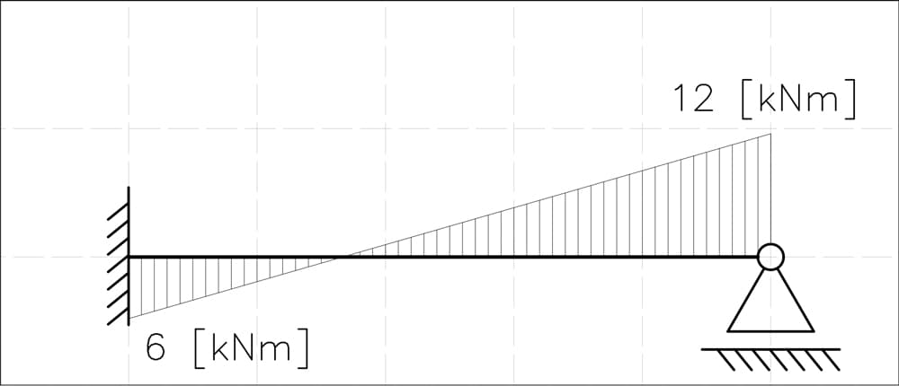
Fig 10. Final bending moment diagram for the original indeterminate system.
Now, having fully reconstructed the original system, we have completed our analysis using the Flexibility Method. Just to make sure we didn’t mess this up, I checked our results using Robot Structural Analysis - here are the results:

Fig 11. Bending moment diagram validation plot.
As you can see, everything matched perfectly. From these calculated bending moments, we could easily determine shear forces and support reactions. However, since these steps are pretty straightforward and we don't want to drag this tutorial out unnecessarily, we'll skip them for now. It's time to move on to our final example - a bit more challenging this time.
5. Example II - Statically indeterminate moment frame
In this example, we're analysing the frame shown in Fig 12 below. Since we've already discussed each step in detail in the previous example, this time we'll skip detailed explanations and focus directly on the process.
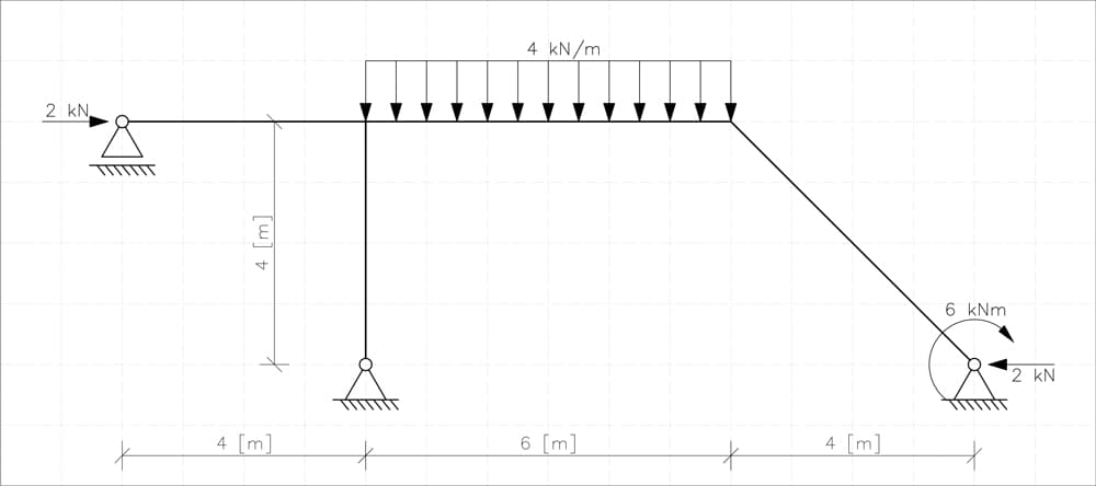
Fig 12. Statically indeterminate frame - example 2.
5.1 Determining the Degree of Static Indeterminacy (DSI)
The first step is straightforward. We calculate the degree of static indeterminacy (DSI):
For our frame, we have:
- 3 supports, two pinned and one roller, so ,
- no internal hinges initially, .
Thus, we have:
5.2 Choose the Primary System and Identify Redundant Constraints
We choose a primary system as presented below by removing two constraints:
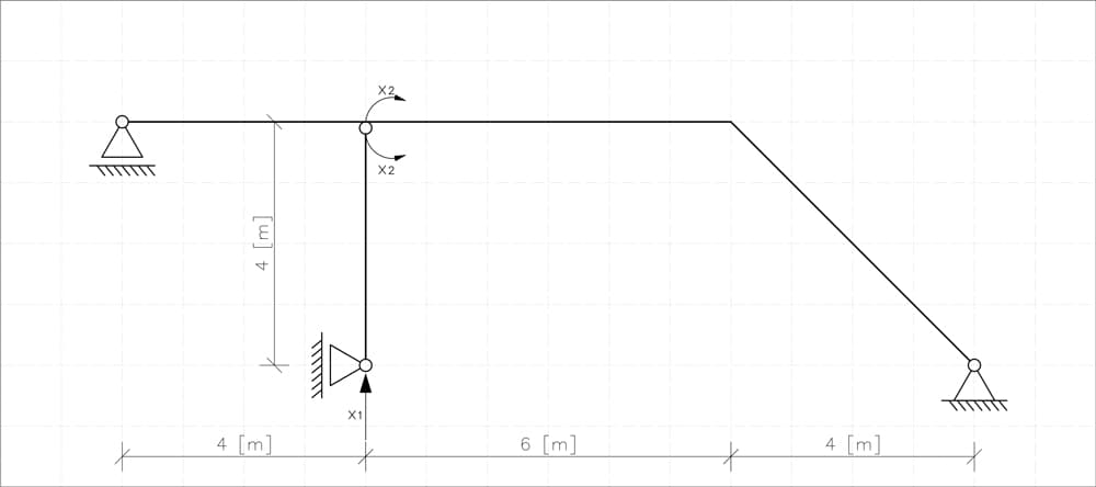
Fig 13. Statically determinate primary system.
- We replace the pinned support at the bottom of the vertical column with roller, removing one vertical reaction ().
- We introduce an internal hinge at the end of the vertical member, removing the moment continuity (). Notice that this hinge does not interrupt the force flow continuity in the horizontal beam.
Why this primary system? Because I wanted to demonstrate that instead of simply removing a support reaction, we can also introduce an internal hinge to create a statically determinate system. Of course, there are multiple valid choices for the primary system, and different selections might lead to slightly different computational paths but ultimately the same final result.
The resulting primary system is statically determinate and ready for further analysis.
5.3 Analysis of States of the Primary System
Let's carefully analyse each loading state separately, solve for the support reactions using equilibrium equations, and construct corresponding moment diagrams.
State
In this state, we apply a vertical unit force () at the bottom hinge support of the vertical column. There are no other external loads.
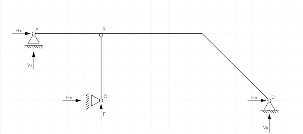
Fig 14. Statically determinate system with unit force applied vertically at C.
We begin by writing equilibrium equations to find the support reactions:
First, we isolate the vertical column below hinge B. By taking moments about point B, we can immediately determine the horizontal reaction at support C:
Knowing , we move to the horizontal beam and inclined member. The absence of horizontal forces ensures .
Next, we calculate the vertical reaction at support D by summing moments around point A:
With known, we can now determine the vertical reaction at support A using vertical equilibrium:
Having determined all the necessary reactions, we can now accurately construct the moment diagram for this state:
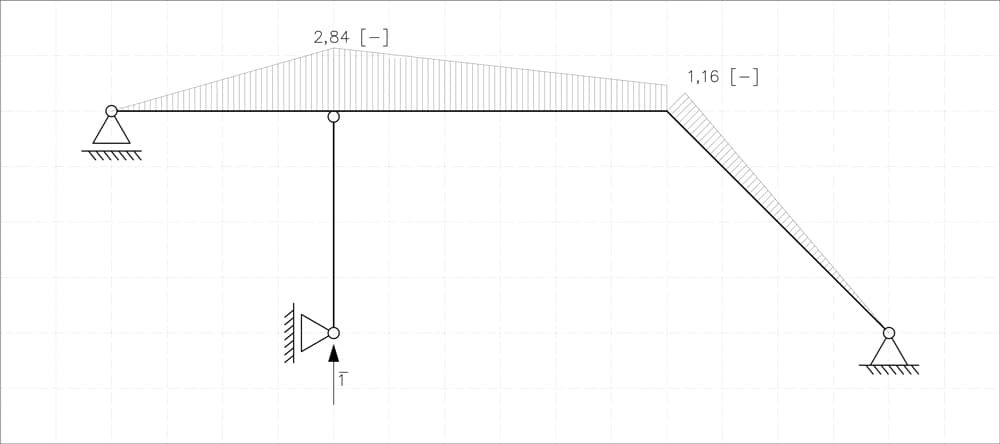
Fig 15. Bending moment diagram for system with unit force applied vertically at C.
State
Now we apply a pair of unit moments () at the introduced hinge (equal and opposite, ensuring equilibrium):
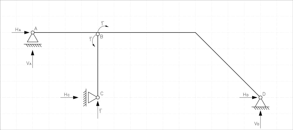
Fig 16. Statically determinate system with unit moments applies at B.
We again begin by writing equilibrium equations to find the support reactions. First, we isolate the vertical member below the hinge at point B and sum moments at point B. This gives us directly the horizontal reaction at support C:
Knowing , we can determine the horizontal reaction at support D from horizontal equilibrium of the entire structure:
There are no vertical loads in this state, hence:
With these reactions determined, the resulting moment diagram can now be drawn, Fig 17.
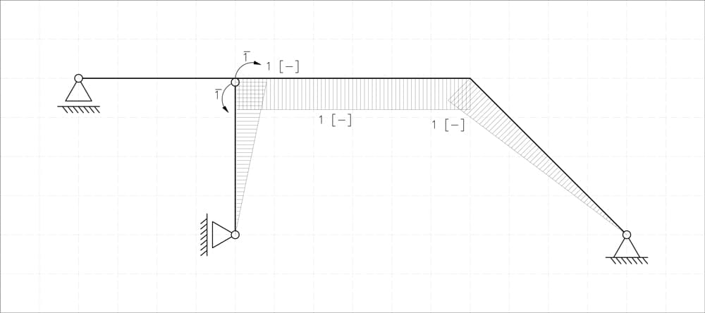
Fig 17. Bending moment diagram for system with unit moments applies at B.
State P
Now let's analyse State P, where our primary system is subjected to external loads.
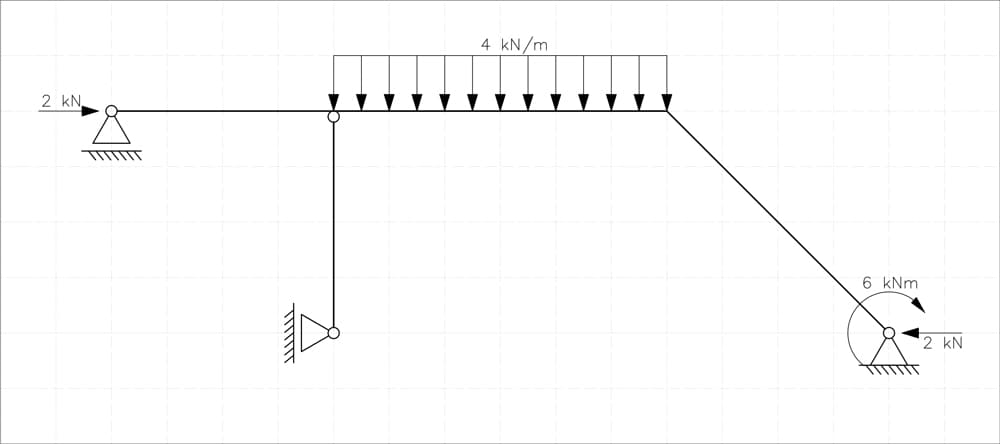
Fig 18. Primary (statically determinate) system, subject to original loads.
Just as before, we start by isolating the vertical member below the hinge, and summing moments at point B:
Knowing that , we can proceed with the horizontal equilibrium of the remaining structure, concluding:
Next, we determine the vertical support reaction at D () by summing moments about support A:
Solving this equation gives us:
Finally, using vertical equilibrium, we find the vertical reaction at support A ():
With all support reactions computed, we are now ready to draw the bending moment diagram for state P.
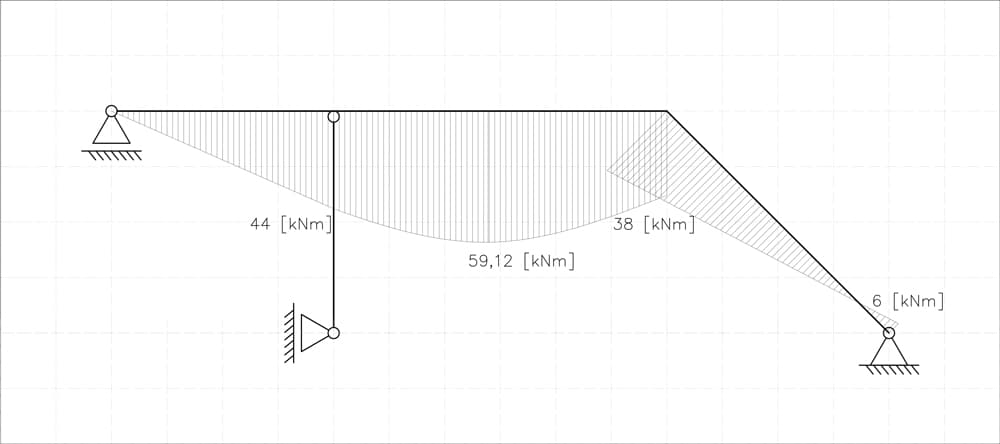
Fig 19. Bending moment diagram for state P.
5.4 Formulating Compatibility Equations
Now that we've analysed all necessary loading conditions and constructed corresponding moment diagrams, it's finally time to set up our compatibility equations. We have two equations, as there are two redundant forces to solve for ( and ):
By solving this system, we'll determine the unknown redundant forces, enabling us to reconstruct internal forces and reactions for the original indeterminate frame.
5.5 Computing Flexibility Coefficients and Displacements Using Vereshchagin’s Method
Now just as before, we'll use Vereshchagin’s graphical integration.
We'll pair our moment diagrams, identify areas and ordinates, multiply them, sum up, and finally get the needed values. Let's jump right into calculations:
- : from diagrams (X₁, X₁)
- and : from diagrams (X₁, X₂)
- : from diagrams (X₂, X₂)
- P: from diagrams (X₁, P)
- P: from diagrams (X₂, P)
Since centroids and areas of basic geometric figures are straightforward to determine, we won’t go into the details of finding them - instead, we'll directly present the calculations.
To simplify the process and avoid manually locating every centroid, we'll use a few handy formulas:
- For two triangles oriented in the same direction
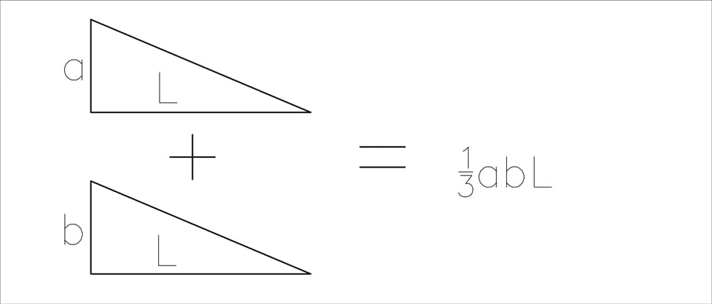
Fig 20. Graphical integration result for two triangles.
- For two arbitrary shapes (excluding parabolas)
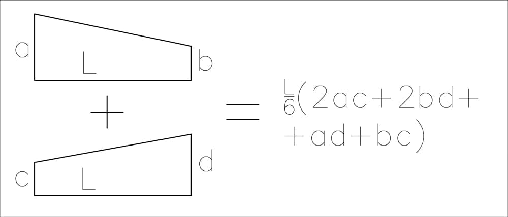
Fig 21. Graphical integration result for two arbitrary shapes.
- For a triangle and a parabola
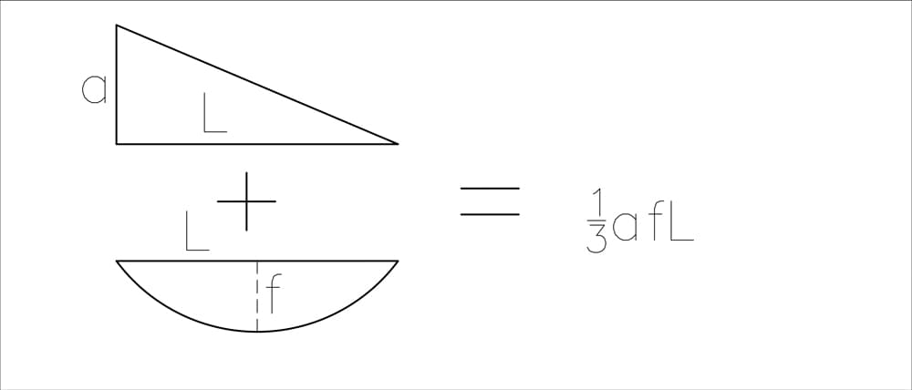
Fig 22. Graphical integration result for a triangle and a parabola.
It’s quite a lot of work, so let’s dive in.
Computing
As a warm-up, let’s start by calculating the flexibility coefficient :
Computing
Next, we determine .
Computing and
Now, we compute and . Since the flexibility matrix is symmetric, we have:
Applying Vereshchagin’s graphical integration method we get:
Computing
Now, we compute the displacement coefficient . Since the State P moment diagram contains parabolic shapes, let’s take a minute to examine how we can strategically divide these diagrams to simplify the calculations.

Fig 23. Break-up of parabolic bending moment diagram shapes using superposition.
According to the principle of superposition, we can split the moment diagram into separate components and then integrate each one individually with the corresponding values from the unit state diagram.
Substituting values from the moment diagrams:
Computing
Now, we compute the displacement coefficient .
5.6 Solving Compatibility Equations
We have now calculated all necessary flexibility coefficients. Let's first summarise our results:
With these values, we rewrite our compatibility equations as:
Substituting numerical values, we have:
We can conveniently eliminate the factor from all terms, simplifying the equations to:
Now, solving this simple system of equations will provide the unknown redundant forces and , finalising our solution process.
5.7 Reconstructing Final Moments Diagram in the Original Frame
With redundant forces and determined, we can now easily calculate the final internal moments at critical points of our frame. This step is straightforward, relying solely on superposition of the three states we've already analysed (states , , and ).
At each selected point, the final internal bending moment will be given by the equation:
Let's systematically compute these moments at key locations:
Now we just plug in the numbers, draw the final moment diagram, and we're done! We'll skip calculating the max value on the parabola since it's a bit more work.
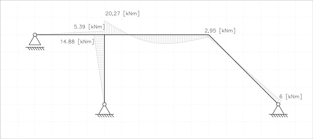
Fig 24. Final bending moment diagram for the original statically indeterminate frame.
Just to be sure, let's compare our diagram with the one from Robot.
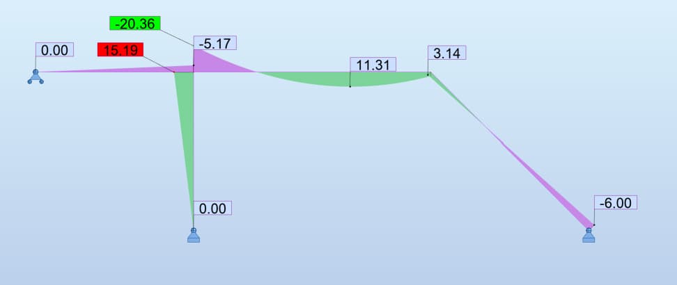
Fig 25. Validation bending moment diagram.
As you can see, the diagrams are almost identical. Any minor differences in results come from numerical approximations and variations in assumed material properties, such as different values of E and I for the cross-sections.
6.0 Wrapping up
Well done for making it to the end of this tutorial—it ended up being quite long, as we covered a lot of ground! You should now have a very good understanding of the Flexibility Method, both the underpinning theory and how to implement it practically.
There’s quite a lot more we could cover here. We could extend this method to handle thermal loads and foundation settlements for example - two cases that regularly arise in real-world structures.
But we’ve probably covered enough for one instalment - perhaps we’ll return to some of these further developments in a future tutorial. I hope you found this helpful. See you in the next one.
Featured Tutorials and Guides
If you found this tutorial helpful, you might enjoy some of these other tutorials.
Analysing Indeterminate Beams and Frames using the Moment Distribution Method
Learn how to draw shear force & bending moment diagrams for indeterminate beams and frames using the moment distribution method

Dr Seán Carroll
3D Truss Calculator – Quick Start Guide
A free 3D truss calculator you can use to find member axial forces, reactions forces and deflections in 3D trusses

Dr Seán Carroll


