An Introduction to Concrete and its Strengths and Weaknesses
![[object Object]](/_next/image?url=%2Fimages%2Fauthors%2Fsean_carroll.png&w=256&q=75)
1.0 An Introduction to Concrete
Concrete is one of the most important and ubiquitous materials in the construction industry globally. Twice as much concrete is used (by weight) as steel, wood, plastics and aluminium combined. Its global usage is estimated at 10 billion tons per year. In this introduction to concrete, we’ll discuss the properties of concrete and what makes it such a versatile construction material.
Fundamentally, concrete is a mixture of cement, water, aggregate and sand. When mixed, they form a slurry or viscous liquid. The mixture undergoes a chemical reaction called hydration and gains strength slowly in a process called curing. The end product is a strong, durable, versatile and relatively cheap construction material. But there are some downsides, we’ll also touch on these in this article.
When you finish this article, the next thing you’ll probably want to learn about is reinforced concrete. I have a full 12 hours course on the design of reinforced concrete structures. You might want to take a look at that, below.
Fundamentals of Reinforced Concrete Design to Eurocode 2
An introduction to ultimate limit state design for bending and shear with optional calculation automation using Python.
After completing this course...
- You will be able to determine design actions using the Eurocodes Basis of Structural Design (EC0) and Actions on Structures (EC1).
- You will understand balanced section design and how to analyse and safely design singly and doubly reinforced concrete sections.
- You will understand how to apply the Variable Strut Inclination Method for shear reinforcement design.
- You will have developed your own reinforced concrete design codes in Python (the Python pathway is optional in this course).
1.1 Historical use of concrete in construction
An introduction to concrete wouldn’t be complete without making reference to its historical usage. The history of concrete as a construction material dates back thousands of years. The earliest known use of concrete dates back to the ancient Egyptians, who used a rudimentary mixture of mud and straw that shared some of the characteristics of the modern concrete and reinforced concrete we know today. This early form of concrete was relatively weak and lacked the strength and durability of modern concrete, but it was still an important step forward in construction technology.
The Romans, who developed concrete more than 1,000 years later, used a mixture of volcanic ash, lime, and water to create strong and durable concrete that could be moulded into various shapes and used to build structures like the Colosseum and the Pantheon.

Fig 1. Pantheon dome, Rome c. 126 AD, [ref].
Roman concrete structures were exceptionally durable due to their incorporation of pyroclastic rock and ash within the mix. These pyroclastic aggregates and ash react with seawater to form a durable crystalline structure. The Roman’s use of concrete and their usage of admixtures that enhanced the durability of their concrete has meant that many of their structures have survived to the present day. After the Roman Empire collapsed, use of concrete became rare until the technology was redeveloped in the mid-18th century.
Over the centuries, concrete technology continued to evolve, with new techniques and materials being developed to make the material stronger and more durable. In the 19th century, the use of Portland cement revolutionised the concrete industry. The introduction of Portland cement, which was patented by Joseph Aspdin in 1824 lead to an explosion in the use of concrete. This new type of cement, which was made from a mixture of clay and limestone, allowed for the creation of concrete with much greater strength and durability.
1.2 Concrete in modern construction
In the 20th century, the use of concrete continued to expand with the development of new technologies and construction techniques like reinforced concrete, pre-casting and pre-stressing. Today, concrete is used for a wide range of applications, from large-scale infrastructure projects like bridges and dams to smaller-scale building projects like homes and commercial structures. Its versatility and durability have made it a popular choice for construction projects of all sizes, and it remains one of the most important building materials in the world. Some of its headline features are:
- As a viscous liquid, it is ‘pourable‘ which means it can be used to generate structural forms that would be difficult or impossible to achieve with other materials.
- It has a high thermal mass which means that it retains heat and can act as a heat sink or heat storage device within structures – this is why underfloor heating is so effective.
- When combined with steel in the form of reinforced concrete, it has excellent load-bearing capacity. Even without steel reinforcement, under the right conditions, unreinforced or mass concrete can have excellent load-carrying capacity – remember the Roman Pantheon dome!
- Depending on the constituents used in the mix, it can be tailored with different characteristics, e.g. high corrosion resistance and high compressive load capacity. Lightweight aggregates can be used to produce lightweight (and low compression capacity) concrete.
- It is non-combustible meaning it provides excellent fire resistance which is of critical importance, particularly in larger structures where premature failure in a fire could be catastrophic.
- Due to their large mass, concrete structures are generally less dynamically excitable than if they were constructed from alternative materials, typically structural steel.

Fig 2. Modern reinforced concrete structures.
2.0 Components and Properties of Concrete
As mentioned above, concrete is a combination of cement, water, aggregate and sand. Each of these constituents, their relative proportions and the prevailing environmental conditions during mixing and curing has a significant impact on the strength and durability of concrete.
2.1 Cement
Joseph Aspdin developed Portland cement and patented it in 1824. It was mass-produced from 1877 with the introduction of the rotary kiln. It is a caustic, fine white/light grey powder produced by mixing and heating chalk and sand at very high temperatures. It is the binding power of cement that fuses aggregates together giving concrete its strength.
Portland cement contains:
- Tricalcium silicate
- Dicalcium silicate
- Tricalcium aluminate
- Tetracalcium aluminoferrite
The proportion of the individual components varies depending on the type of cement but and make up over 70% of Ordinary Portland Cement (OPC). The calcium silicate reacts with water during curing in a chemical reaction called hydration.
There are also a number of cement replacements in common use today. These can be used to partially replace the cement content in a mix. Pulverised fuel ash (PFA) or fly ash and ground granulated furnace slag (GGBS) can be used as partial cement substitutes and have a number of advantages such as improving mix workability as well as being derived from waste products thereby improving the sustainability of the concrete.
2.2 Hydration and strength gain
The chemical reaction responsible for strength gain is called hydration. This is an exothermic reaction; the increase in temperature during curing can lead to significant residual stresses developing within the concrete, which can lead to cracking.
Care must be taken during curing to ensure heat can be dissipated – this is particularly important for large concrete pours where significant heat will be generated. Typically as the depth of concrete being poured is increased, the larger is the rise in temperature observed. For large-scale concrete pours, serious consideration must be given to heat dissipation and management during curing. In many cases, this so-called heat of hydration can be dissipated during curing by keeping the surface of the concrete moist.
Upon mixing, when the cement comes into contact with water, the tricalcium aluminate reacts with the water to form an aluminate-rich gel. This gel reacts with sulphates to form a crystalline structure called ettringite. This characterises the initial phase of the hydration reaction and lasts for several hours. As the curing process continues, the concrete mix becomes less and less workable.
The process of hydration continues with the formation of calcium silicate hydrate and calcium hydroxide or calcite. This produces an alkaline environment that helps prevent steel reinforcement bars from corroding.
Concrete continues to gain strength over time as the hydration process continues. The initial rate of strength gain is high which can allow supporting structures (known as formwork and falsework) to be removed at 7 or 14 days after casting.
At 28 days after casting, the concrete has achieved almost all of its compression capacity. We typically specify concrete by its compression strength at 28 days (discussed further below). However, it will continue to gain strength at a slow rate for some time thereafter.
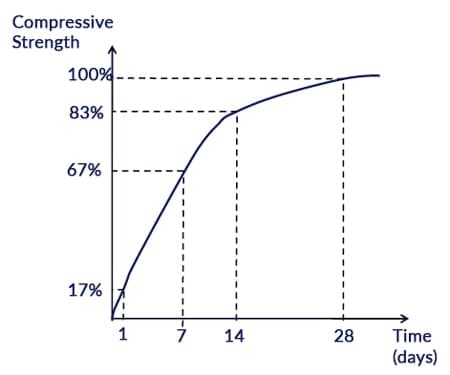
Fig 3. Typical concrete strength gain over time.
2.3 Water/cement ratio
The water/cement (w/c) ratio during mixing is a crucial determinant of the strength of the cured concrete. A high w/c ratio results in a low-viscosity mix that is generally easier to pour. Such a mix would be referred to as being more workable. However, the resulting concrete will have a high porosity after hydration and therefore a lower compression strength. This is because a high w/c ratio means that there is more water in the mixture to hydrate the cement, which leads to a lower concentration of cement. This, in turn, results in lower strength and higher porosity, which can make the concrete more susceptible to cracking and deterioration over time.
Conversely, lower w/c ratio mixes are more difficult to work but lead to less porosity and higher strengths. However, if the w/c ratio is too low, pouring the concrete can become difficult and this can lead to incomplete compaction leaving voids in the cured concrete.
The optimal w/c ratio for a concrete mixture depends on several factors, including the type of cement used, the size and distribution of the aggregate, the desired strength and durability and the environmental conditions in which the concrete will be used. In general, the w/c ratio for most concrete mixtures is between 0.4 and 0.6, with the exact value being determined by the specific requirements of each project
2.4 Aggregates
The aggregates used to make concrete should be a mixture of coarse and fine aggregate. The aggregates constitute approximately to of the concrete by volume. The size distribution and shape of the aggregate can significantly impact its properties and the performance of the final concrete.
Aggregate size distribution affects the workability of the concrete mixture. If the aggregate size distribution is not appropriate, the concrete mixture can become too viscous or too fluid. When the aggregate size distribution is optimised, the concrete mixture will have the right balance of workability and stability, allowing it to be easily placed, compacted, and finished. Aggregate size distribution also affects the durability of the concrete by influencing the porosity and permeability of the concrete, which can impact its resistance to water and chemical attack.
2.5 Concrete compaction during casting
During concrete pouring, it is critical that void formation within the body of the concrete is minimised. Heavily reinforced concrete with elaborate reinforcement cages are particularly prone to voids as it can be difficult to ensure the concrete flows completely around the cages.
Void formation can be minimised by ‘compacting’ the concrete during the pouring process. This involves manual vibration and tamping of the concrete to help it flow completely around the steel reinforcement cages and formwork. Voids can reduce the strength of the concrete and reduce the bond between concrete and steel, diminishing their composite action.
Compaction is usually achieved with mechanical poker vibrators that are lowered into the concrete. Care must be taken not to over-vibrate the concrete as this can lead to separation with water rising to the surface, inhibiting the hydration reaction.
2.6 Strength classification
Concrete typically has a density of with reinforced concrete being at the top of this range. Typical values for the compressive strength of concrete range from but strengths as high as can be found in high load applications.
The term compressive strength actually has a very specific meaning when it comes to concrete. The strength of concrete is indicated by its class. For example, a concrete classed as C25/30 would have a characteristic cylinder crushing strength of and a cube strength of . The ‘C’ indicates normal weight concrete whereas an ‘LC’ would indicate lightweight concrete.
The cylinder strength is determined by crushing a sample concrete cylinder in diameter and high. The cube strength is determined by crushing a cube.
These values are the characteristic values obtained from crushing a number of sample specimens. The characteristic cylinder strength is the compressive stress below which less than are likely to fail. Or put another way, of samples would be expected to have a compressive capacity higher than the characteristic value.
The characteristic cylinder strength is a fundamentally important parameter for the design of reinforced concrete structures. To understand its role in design we need to understand the stress-strain behaviour of concrete.
2.7 Stress-strain behaviour
Concrete is not a perfectly linearly-elastic material. This means that the relationship between concrete stress and strain is not strictly linear as it is for steel (up to the elastic limit). The image below, Fig 4(a), shows a typical stress versus strain curve obtained from testing a concrete specimen in compression.
Unlike a perfectly linearly elastic material, the stress-strain relationship is characterised by a parabolic curve until a compressive strain of approximately is reached, denoted by . This is accompanied by an ultimate design compressive stress of:
where is the characteristic compressive cylinder strength of the concrete at 28 days, is the material partial factor of safety for concrete and the factor allows for long-term effects and the difference between the bending strength and the cylinder crushing strength of the concrete.
We use partial material factors to represent the uncertainty of achieving the stated characteristic strength of the material (steel or concrete). Typically for concrete, , thus for a concrete mix with a specified cylinder strength of , the design compressive strength is reduced to,
Note that after the design compressive stress is reached, no further stress increase is observed, yet the strain continues increasing until a maximum strain value of approximately is reached, denoted by . This is the ultimate compressive strain and represents the point at which concrete crushing will occur. The horizontal portion of the stress-strain graph represents classic plastic behaviour, whereby the strain is increasing at a constant level of stress. This has significant implications for the design of concrete.
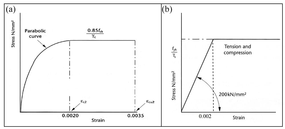
Fig 4. Stress-strain behaviour for (a) concrete and (b) steel.
3.0 The Behaviour of Concrete in Service
Up to this point, we’ve really only focused on the material properties of concrete and the role its constituent elements play in the strength and durability of the cured concrete. However, we also need to be aware of the behaviour of concrete in service and how it responds to loading. As we’ll see, there are some quirks that we really need to be aware of!
3.1 Shrinkage and Thermal Movement
Concrete will shrink as it cures and continues to dry out over time. This loss of water through evaporation leads to a reduction in volume or shrinkage and can continue for months after casting. Subsequent wetting and drying of the concrete can also lead to expansion and contraction.
Since hydration is an exothermic reaction, further thermal shrinkage can occur during curing. Thermal shrinkage can be reduced by managing the temperature during curing. There are a number of practical ways that this can be achieved,
- Keeping the cement content as low as possible or using the cement replacements discussed above (PFA or GGBS) can reduce the heat of hydration.
- Using chilled water during mixing and keeping aggregates cool before mixing.
- Casting the concrete using steel shutters (forms into which the concrete is poured) and spraying the shutters with water. The evaporating water will draw heat away from the curing concrete much the same way sweat on the skin cools the body.
- Strike (remove) formwork (another name for forms concrete is cast into) early to allow heat to escape.
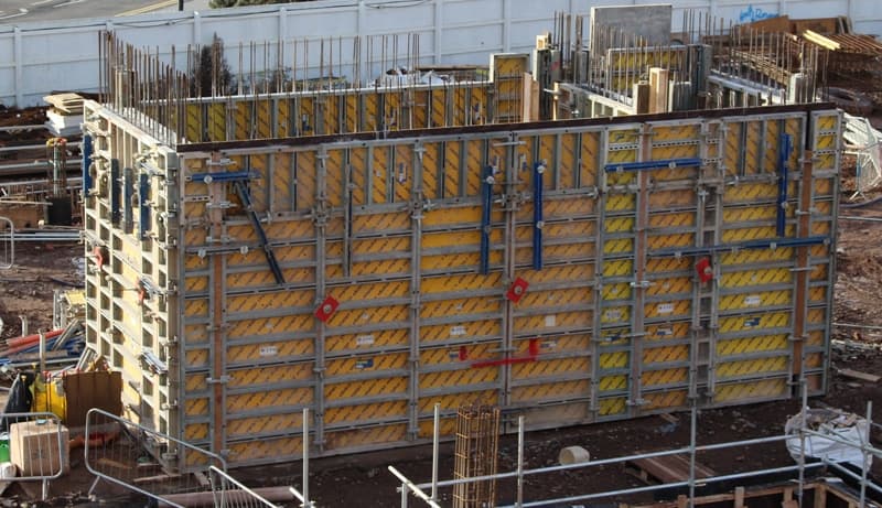
Fig 5. Formwork used to cast a series of reinforced concrete walls.
Ultimately shrinkage due to water evaporation and thermal movement are problems because they cause changes in volume. Since concrete is a brittle material, this can lead to cracking. Cracking is unsightly and can expose internal steel reinforcement to corrosion.
Keep in mind changes in volume will only cause cracking of the concrete if it is restrained. If the concrete structure is free to contract, cracking should be minimal. However, this is usually not practical, which is why efforts must be made to minimise heat buildup during hydration and premature drying out after casting.
For larger, more complex concrete structures, significant attention must be given to how the concrete casting process should be phased and managed to reduce cracking. In addition to the measures discussed above, joints should be designed into the structure that allows shrinkage and thermal movement, relieving stresses within the concrete that would otherwise lead to cracking.
3.2 Creep
Creep is a slow continuous deformation of the concrete structure under the influence of sustained loading. Creep can be particularly apparent in long-span concrete beams and slabs. The image below illustrates a typical strain profile of concrete under constant loading. The initial elastic strain (and deflection) is observed relatively quickly. However, further creep strain is experienced at a much slower rate thereafter. Creep is a plastic deformation, i.e. it increases under constant loading. Therefore, if the loading is removed, only the elastic strain/deflections are recovered.
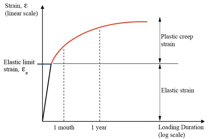
Fig 6. Typical long-term strain profile for concrete under constant load.
In flexural members such as beams and slabs, for example, creep can lead to very large deflections. Creep deflection sometimes referred to as long-term deflection, can be several times larger than elastic deflections. If not carefully considered at the design stage, creep deflection can cause cracking, damage to non-structural elements as well as the development of unintended load paths (e.g. slabs/beams bearing onto ‘non-structural’ partitions). Deflections due to creep are approximately proportional to the intensity of sustained loading and inversely proportional to concrete strength.
4.0 Environmental cost and sustainability
Engineers and the choices they make have a significant impact on the environment. Engineers, therefore, have a responsibility to promote sustainable development and promote sustainable methods of construction and the use of sustainable materials whenever possible.
Concrete has several positive attributes from a sustainability point of view. It is typically manufactured locally to its point of use and utilises relatively plentiful raw materials. Therefore the associated with transportation is relatively low.
It has a high thermal mass. As such, when this is taken into consideration in the services design of a building, this can result in lower building heating and cooling costs as the concrete elements can absorb and retain heat.
Concrete structures are also exceptionally robust, generally requiring little maintenance (e.g. Roman structures still with us). With long design lives, the cost of refurbishment and replacement can be reduced.
However, these positive characteristics must be balanced against the large environmental cost of cement production, which emits large quantities of . We have mentioned above that there are cement replacements such as PFA and GGBS that are byproducts from other manufacturing processes. These improve the sustainability of concrete. However, the vast majority of the world’s concrete still uses ordinary Portland cement, which requires high temperatures (and therefore energy usage) to produce.
Cement production accounts for approximately of global emissions and is the third largest source of man-made after transport and energy production. Approximately of are emitted for every ton of cement produced. This makes up of the emissions associated with the average concrete mix.
This actually compares favourably with steel which it’s estimated generates approximately tonnes of per tonne of steel. However, it’s the vast quantities of concrete (and therefore cement) used globally that lead to concrete having such a large carbon footprint.
As awareness of the need to adopt more sustainable construction practices continues to grow, we should expect to see greater justification being required for the use of concrete on construction projects. But for better or for worse, right now, there is very little that can compete with concrete in terms of versatility, availability and cost.
5.0 Wrapping up
In this introduction to concrete, we’ve focused on its role in construction, both historically and today and we’ve explored its properties. But this is really only half of the story. To fully understand the role of concrete as a construction material we need to understand how it acts compositely with steel reinforcement in reinforced concrete structures.
In the next concrete tutorial, we’ll introduce steel reinforcement into the picture and dive into the mechanical models we use the model and predict the structural performance of reinforced concrete structures.
Remember if you want to dive straight into studying reinforced concrete and how we design code-compliant structures, you can take a look at my course, Fundamentals of Reinforced Concrete Design to Eurocode 2. That’s all for now – I’ll see you in the next one.
Dr Seán Carroll's latest courses.



Featured Tutorials and Guides
If you found this tutorial helpful, you might enjoy some of these other tutorials.
Steel Truss Design to Eurocode 3
Learn how to design one of the most common structural forms - the steel truss

Callum Wilson


