How to Analyse Indeterminate Beams using the Moment Distribution Method
![[object Object]](/_next/image?url=%2Fimages%2Fauthors%2Fsean_carroll.png&w=256&q=75)
In this tutorial we’ll explore the moment distribution method. This is an excellent technique for quickly determining the shear force and bending moment diagrams for indeterminate beam and frame structures. In this tutorial, we’ll focus on applying the moment distribution method to beams.
We’ll start by getting a clear understanding of the steps in the procedure before applying what we’ve learned to a more challenging worked example at the end. If you’d prefer to watch me explain the solution, you can watch video below.
This tutorial is based on my course, Indeterminate Structures and the Moment Distribution Method. After you finish this tutorial, you can go there to keep learning.
Indeterminate Structures & The Moment Distribution Method
Unlock indeterminate structures using the moment distribution structural analysis method.
After completing this course...
- You will have a deep understanding of how structures respond to loading.
- You will clearly understand the methods used to analyse statically indeterminate beams and frames.
- You will be able to analyse both non-sway and sway frames – essential when designing real world structures.
If you’re reading this, I’m assuming you’re already comfortable drawing shear force and bending moment diagrams for statically determinate beams. If you’re not, work your way through this tutorial first.
1.0 Introduction to the Moment Distribution Method
Let’s start by summarising the key features of the moment distribution method; the technique seeks to identify the bending moments at internal joints through an iterative process of applying balancing and redistribution moments.
Iterations continue, successively reducing and moment imbalance, until moment equilibrium is achieved at all joints in the structure. With these internal moments established, span moments, shear forces and support reactions are determined using free body diagrams and simple statics.
We start by fixing all internal joints against rotation. This is often referred to as locking the structure. In a multi-span beam, this results in a series of beam segments, isolated from each other by locked joints. Next, we determine the bending moments that develop at each locked joint as a result of the loading on each beam segment. Typically there will be a moment imbalance at each joint. At this point we enter the iterative moment balancing process; for each joint in turn, we:
- apply a balancing moment to eliminate the imbalance
- distribute the balancing moment between the members meeting at the joint, in proportion to their flexural stiffnesses
- carry over 50% of the distributed moment to the other end of each of the members meeting at the joint -assuming the adjacent joint is capable of resisting moments – we’ll clarify this below)
This carry-over moment will now unbalance the joints in the structure again. This means we need to repeat the balance and distribution process. This process repeats over and over again, however, with each iteration the moment imbalances in the structure become smaller and smaller.
As usual, the only real way to make sense of this is to watch it in action, so let’s work our way through a simple example.
2.0 A Simple Example
Consider the simple two-span continuous indeterminate beam in Fig 1. below. This beam is statically indeterminate because there are more than three unknown reactions. So, we can’t determine their values with only 3 equations of statics. This makes the structure a prime candidate for a moment distribution analysis.

Fig 1. Two-span continuous indeterminate beam.
2.1 Locking the joints against rotation
The first step is to lock any joint not already fixed against rotation, so in this case, that’s joint B. The structure is now essentially two isolated spans, AB and BC with the loading on one span having no impact on the other.

Fig 2. Beam with all joints fixed against rotation.
Next, we can determine the moments that develop at each locked joint due to the span loading in each beam segment. The quickest way to do this is by using tables of fixed-end moments. A table of common fixed-end moments is provided, Fig. 3.
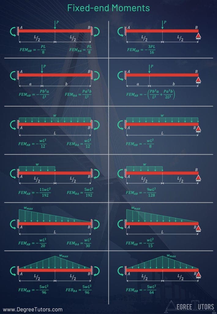
Fig 3. Common fixed-end moments.
We can see that in this case, the joint moments that develop due to the loading between AB are . The joint moments induced by the loading on BC are . Another way to think about the fixed-end moments is that they’re the reaction moments that would develop at the fixed ends, in response to the applied loading.
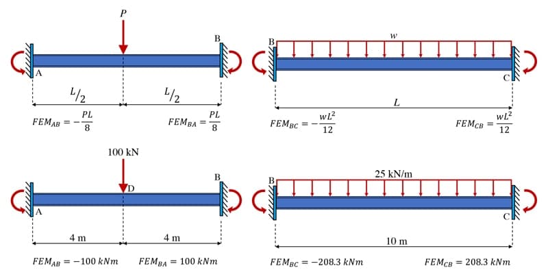
Fig 4. Fixed-end moments that develop at the locked joints.
2.2 Balancing the joint
If we now focus on joint B, we can see a moment imbalance due to the clockwise from AB and the counter-clockwise from BC. If we now imagine releasing this joint, it would, in theory, experience a net counter-clockwise moment of . In response to this, we will add a clockwise balancing moment of to eliminate the moment imbalance, Fig. 5.

Fig 5. Moment imbalance at B and the applied balancing moment.
2.3 Distributing the balancing moment
In adding the balancing moment to the joint, it must be distributed between all of the members that meet at the joint. This distribution is done in proportion to the flexural stiffnesses of the members meeting at the joint. We talk more about how these stiffnesses are determined below but for now, let’s just assume that beam segment AB is twice as stiff as segment BC.
This would mean that the balancing moment is distributed between AB and BC in a 2:1 ratio. So, into member AB and into BC. As a result, the joint is now balanced with moments of balancing each other on either side of the joint.
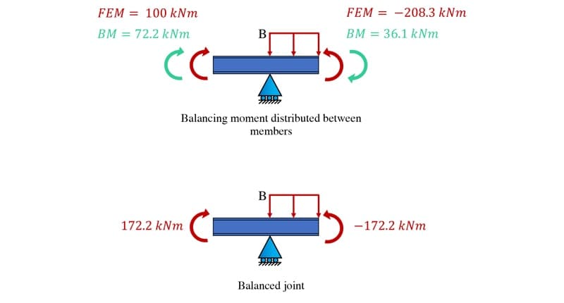
Fig 6. Distributing the balancing moment.
2.4 The carry-over moment
We’re not finished just yet, the final step is to propagate the carry-over moment to the opposite ends of each beam segment. Since the structure has fixed supports at A and C, we can’t apply balancing moments at B without a corresponding moment developing at the outer supports.
As the supports are fully fixed, of the balancing moments will be carried over, Fig 7. Had A or B been a pin or roller support, which offers no resistance to rotation, the carry-over moments would be zero.
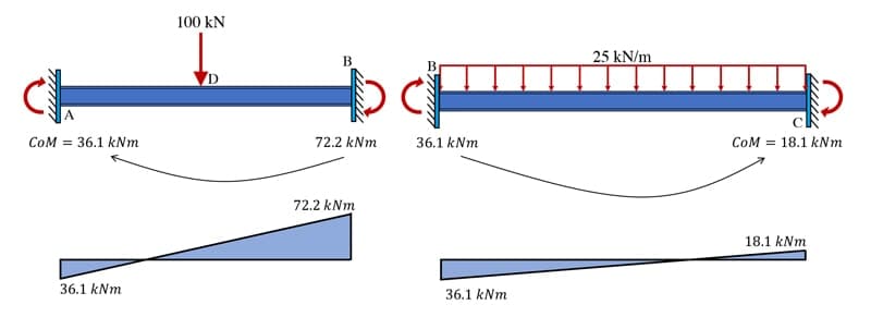
Fig 7. Carry-over moments.
Now we can add up the final moments at each joint, Fig. 8. This was a relatively simple distribution that only required a single balancing iteration. For structures with more than one internal locked joint, multiple balancing iterations are required – we’ll see an example of this below.

Fig 8. Adding up the final joint moments for the structure.
For more complex, multi-iteration structures, we can use a table to help keep track of the analysis. A simple table tracking this analysis is shown below, Table 1.
| Joint | A | B | B | C |
| Member | AB | BA | BC | CB |
| Distribution Factor | 0.66 | 0.33 | ||
| Fixed-end moments | -100 | 100 | -208.3 | 208.3 |
| Distribution | 72.2 | 36.1 | ||
| Carry-over | 36.1 | 18.1 | ||
| Final | -63.9 kNm | 172.2 kNm | -172.2 kNm | 226.4 kNm |
3.0 Relative Stiffnesses and Moment Distribution Factors
In the last example we assumed a ratio of stiffnesses between the beam segments. This was just so that we could work through an analysis from start to finish, without getting distracted.
We actually need to more carefully evaluate the relative stiffness of each member. We’ll discuss how to do this next. The flexural stiffness of a beam element depends on the following factors:
- The beam material, captured using Young’s modulus,
- The cross-section shape, captured with the second moment of area,
- The length of the beam between supports,
- The degree of rotational restraint at supports.
In terms of rotational fixity, the beam segment will have one of two possible stiffnesses. If there is complete rotational fixity or resistance to rotation provided at both ends of the beam, the stiffness will be,
However, if one end of the beam is pinned and therefore has no resistance to rotation at that end, the beam stiffness will be,
We can more readily summarise the possible fixities and their associated stiffnesses graphically, Fig 9.
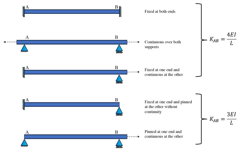
Fig 9. Beam element stiffnesses based on rotational fixity at supports.
With this additional information, let’s return to our example question and update it with the correct element stiffnesses. Considering AB first; it’s fixed against rotation at A and since it’s continuous over support B, it will have a stiffness of,
The same reasoning applies to the segment BC and so its stiffness will be,
Now we can calculate more accurate distribution factors governing the degree to which the balancing moment is distributed into each member. The distribution factor for member AB is given by,
Since there is only two members meeting at joint B, we know that the distribution factor for BC is . For completeness however, we’ll also state the complete expression,
Repeating the distribution analysis with the correct distribution factors reveals the actual final set of support moments for the structure, Table 2.
| Joint | A | B | B | C |
| Member | AB | BA | BC | CB |
| Distribution Factor | 0.56 | 0.44 | ||
| Fixed-end moments | -100 | 100 | -208.3 | 208.3 |
| Distribution | (0.56×108.3) =60.65 | (0.44×108.3)=47.65 | ||
| Carry-over | 30.33 | 23.83 | ||
| Final | -69.67 kNm | 160.65 kNm | -160.65 kNm | 232.13 kNm |
4.0 Reactions, Shear Forces and Bending Moments
Our analysis so far has revealed the bending moments at each joint. But to complete the analysis and produce shear force and bending moment diagrams, we have more work to do.
Fortunately, the missing information can be easily obtained using simple statics and free body diagrams. Consider a free body diagram of beam segment AB, Fig 10.
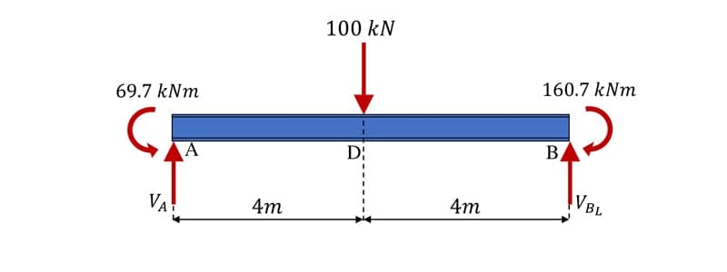
Fig 10. Free body diagram of beam segment AB.
We have two unknowns here, the shear forces at A and B. We can determine the shear force immediately to the left of B, , by evaluating the sum of the moments about A. We’ll assume clockwise moments are positive.
Next we can evaluate the sum of the vertical forces to determine .
Because the beam segment is subject to a single point load, we know there will be a peak moment under the point load and that the moment will vary linearly between this peak and the two support moments.
Similarly, we know that the shear force diagram will consist of two horizontal straight lines. At this stage in the process, you’ll need to have a good understanding of basic shear force and bending moment diagram construction – review this tutorial now, if needed.
We can determine the internal bending moment under the point load by making a cut in the structure at this location to reveal the internal moment, , Fig 11.

Fig 11. Free body diagram of beam segment AD
Evaluating the sum of the moments about the cut yields,
We can repeat this process now for beam segment BC, Fig. 12.
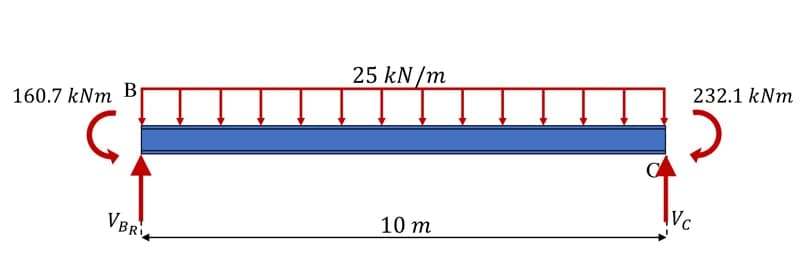
Fig 12. Free body diagram of beam segment BC.
Evaluating the sum of the moments about B first.
Now evaluating the sum of the forces in the vertical direction.
This beam segment is subject to a uniformly distributed load (UDL) which means the shear force will vary linearly between on the left and on the right.
The location of maximum moment will be where the shear force is zero. So, to determine this distance, to the right of B, we can divide the shear on the left by the rate at which it’s reducing, , due to the UDL,
This is where we can make our cut to reveal the maximum span moment, Fig. 13

Fig 13. Free body diagram of beam segment identifying the location of the maximum moment.
Evaluating the sum of the moments about the cut location,
Now we have all the information we need to sketch out the complete shear force and bending moment diagrams for this beam, Fig 14.
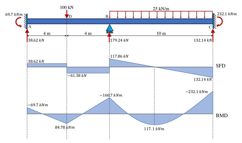
Fig 14. Sketch of the shear force and bending moment diagram.
This analysis walkthrough has demonstrated the complete moment distribution method. You should now have a good understanding of the various steps involved and recognise the potential this technique offers for manual analysis of both beam and frame structures. In the next section, we’ll work through a slightly more complex beam example that will require us to implement a multi-iteration solution.
5.0 Moment Distribution Method: Multi-iteration Worked Example
For this example, consider the multi-span continuous beam shown below, Fig 15. We will again assume is constant for this beam. With this example, we’ll see that a relatively complex span and loading arrangement can be handled quite quickly using the moment distribution process.
With some practice, the processing can become very streamlined and somewhat formulaic to implement. You can continue reading through the solution or watch the full solution video below.

Fig 15. Multi-span continuous beam.
5.1 Member Stiffnesses
Based on our earlier discussion of element stiffnesses, we can state the following:
We don’t calculate a stiffness for segment DE because no balancing moment will be transmitted into this segment. This is because we already know what the final moment will be at this location due to the fact that it’s a cantilever.
5.2 Distribution Factors
We calculate the distribution factors for each internal joint in the usual way, again noting specifically that no balancing moment will be distributed into DE and therefore the distribution factor for DC will be 1.
5.3 Fixed-end Moments
Considering segment AB first, Fig 16, the fixed-end moments are obtained as,
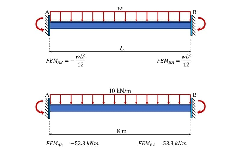
Fig 16. Fixed-end moments, segment AB.
Next, we can evaluate beam segment BC, Fig 17.
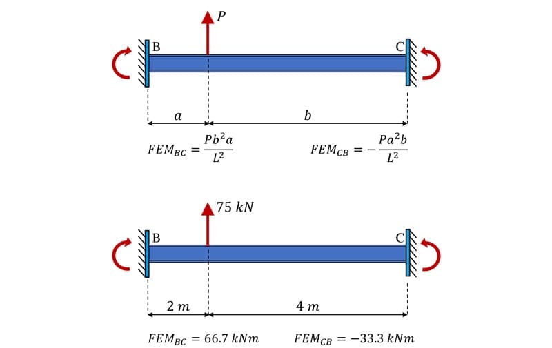
Fig 17. Fixed-end moments, segment BC.
When evaluating the fixed-end moments for segment CD we fix joint C as usual. However, since the beam is free to rotate to the right of D, i.e. it is not restrained due to the fact it’s a cantilever to the right of D, we leave this joint pinned. So, the fixed-end moment, is calculated assuming a propped cantilever model, Fig 18.
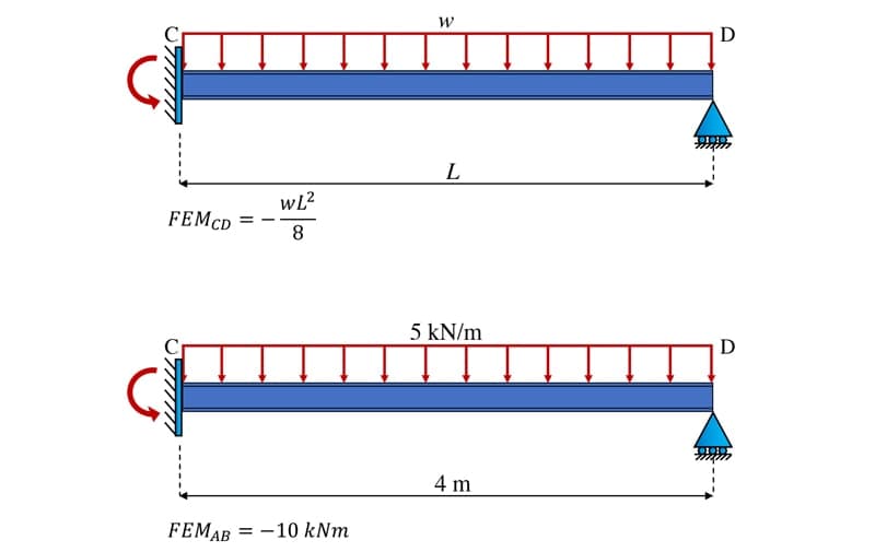
Fig 18. Fixed-end moments, segment CD.
Finally we can determine the fixed-end moments at DE and ED which are really just the cantilever moments evaluating from simple statics.
5.4 Moment Distribution
Now that we’ve established all of the input information, we can construct the moment distribution table and process the distribution, Table 3. Unlike our previous example, because this structure has multiple internal joints, we’ll need to work through multiple balancing and distribution iterations to progressively reduce the moment imbalance at each support.
The first four rows of the table contain all of the structure and loading information we’ve just determined. Thereafter we are:
- Identifying the out of balance moment at each joint and calculating the balancing moment to distribute into each member based on the distribution factors.
- Once all joints are balanced, we carry over of the balancing moment to adjacent locked joints. Note again, that there is no carry-over moment applied to DC since the cantilever moment at this location is already determined.
- The carry-over moments have unbalanced the joints again, so we need to determine a new balancing moment for each joint, so we return to step one and repeat the process.
This process continues until the balancing moments being applied are sufficiently small. Practically, we can stop balancing once the moments have reduced to about 1 or 2 percent of the initial fixed-end moments. This leaves us with balanced internal joints.
| Joint | A | B | B | C | C | D | D | E |
| Member | AB | BA | BC | CB | CD | DC | DE | ED |
| Distribution Factors | 0.43 | 0.57 | 0.47 | 0.53 | 1 | 0 | ||
| Fixed-end Moments | -53.3 | 53.3 | 66.7 | -33.3 | -10 | 0 | -50 | 50 |
| Distribution | (-120)-51.6 | (-120)-68.4 | (43.3)20.35 | (43.3)22.95 | 50 | |||
| Carry-over | -25.8 | 10.18 | -34.2 | 25 | ||||
| Distribution | -4.38 | -5.8 | (9.2)4.32 | (9.2)4.88 | ||||
| Carry-over | -2.19 | 2.16 | -2.9 | |||||
| Distribution | -0.93 | -1.23 | 1.36 | 1.54 | ||||
| Final | -81.29 kNm | -3.61 kNm | 3.61 kNm | -44.37 kNm | 44.37 kNm | 50 kNm | -50 kNm | 50 kNm |
At this point, we can use free body diagrams and the equations of statics to evaluate the remaining unknown shear forces and bending moments. I won’t go through that step-by-step here because the process is pretty much the same as that demonstrated in the previous example. If you want to see every step, you can watch the solution video where I go through the complete process. The final shear force and bending moments diagrams are sketched below, Fig. 19.
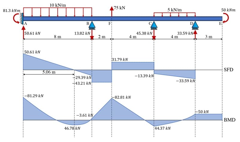
Fig 19. Sketch of the final shear force and bending moment diagrams.
As a means of confirming this result, we can input this structure into our 2D beam and frame Python solver and obtain the same result, admittedly a lot quicker, Fig 20.
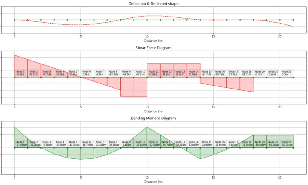
Fig 20. Graphical output from the 2D beam and frame solver we built in this course.
I hope this tutorial has given you a sense of how useful the moment distribution method can be. It’s a particularly handy tool for sub-frame analysis, allowing shear forces and bending moments to be quickly established.
In practice, you’re probably more likely to use a software programme to perform the analyse – not least because it makes analysis iterations faster, when for example, you need to alter the loading on the structure. Having said that, it’s still a good idea to have a manual analysis technique up your sleeve!
Although we’ve demonstrated the key features of the moment distribution method here, there’s more to cover in order to analyse frame structures, particularly sway frames. If you want to continue studying the moment distribution method with me, take a look at the following courses:
- Indeterminate Structures and the Moment Distribution Method (start here first)
- Moment Distribution Method: Analysis Bootcamp (then take this second)
That’s all for now, see you in the next one.
If you want full access to the complete EngineeringSkills course (and code!) library, for one low annual fee, consider subscribing to the All Access Membership or Lifetime Access Membership if you never want to pay for another course again :)
All Access Annual Membership
Learn, revise or refresh your knowledge and master engineering analysis and design
Access Every Course and Tool
- Over 998 lectures & over 205 hours of HD video content
- Access Member's Only 'deep dive' tutorials
- Access all downloads, pdf guides & Python codes
- Access to the StructureWorks Blender Addon
- Packed development roadmap of courses & tools 🏗️
- Price Guarantee – avoid future price rises as we grow
- Priority Q&A support
- Course completion certificates
- Early access to new courses
Dr Seán Carroll's latest courses.



Featured Tutorials and Guides
If you found this tutorial helpful, you might enjoy some of these other tutorials.
Building a Parametric Frame Analysis Pipeline with OpenSeesPy and OpsVis
We’ll build a script to perform 2D elastic frame analysis and use OpsVis for fast visualisation of model behaviour

Dr Seán Carroll
A practical guide to floor vibration serviceability assessment
Part 1: Understanding human-induced floor vibration and assessing acceptability

Dr Seán Carroll

