What is a Truss?
![[object Object]](/_next/image?url=%2Fimages%2Fauthors%2Fsean_carroll.png&w=256&q=75)
What is a Truss?
A truss is a structure that consists of a collection of structural elements connected at pin joints or nodes. In theory, the pin joints provide no rotational resistance and behave as hinges. In practice, this is not always the case. The benefit of a truss is that the members are predominantly axially loaded. This means they are either in compression, tension or have no force, so-called zero-force members. This makes trusses a particularly efficient structural form. In this tutorial, we’ll discuss common forms of truss, their features, approximate methods of analysis and the key assumptions that relate to our analysis. If you want to know how we can manually analyse trusses to determine the forces that develop in each member, I’ve written a tutorial on that here.
If you’re interested in truss behaviour, check out our free truss analysis toolbox below. There is no substitute for understanding the fundamental mechanics of a truss, but having access to an easy to use truss calculator does make life a little easier!
ONLINE TRUSS TOOLBOX 🛠️
Try our free truss analysis toolbox for calculating reactions, axial forces and deflections. A handy tools for students and professional engineers.
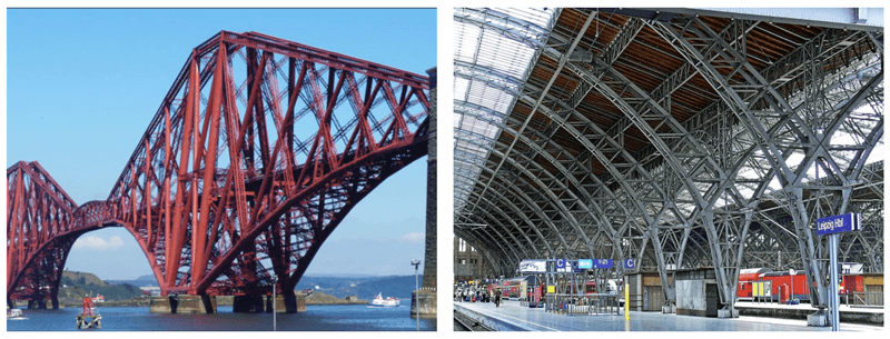
Forth Bridge demonstrating truss action (left), Truss roof structure (right)
We see trusses all around the built environment. They are simple, yet incredibly efficient structures capable of spanning very large distances while using relatively little material. This means they are lightweight with very favourable strength-to-weight ratios. It’s this efficiency that makes them well suited as roof and bridge structures.
Common Truss Types
There are many common forms or patterns of truss that have emerged in response to different use cases. Some of the most common are the Pratt, Howe, Warren and Modified Warren. The truss pattern refers to the arrangement of internal vertical and diagonal members. The top and bottom horizontal members are often referred to as truss chords or booms.
Pratt
The Pratt truss (first proposed by Thomas Pratt in 1844) is one of the most common forms of truss and is made up of vertical and diagonal members that form an ’N’ shape or pattern. The diagonal members are arranged so that they only develop tensile forces. As such, they can be designed to resist axial tension only, avoiding the need for a compression buckling analysis. The vertical members in a Pratt truss develop compression forces. This means they will typically be more robust and capable of resisting buckling. The simplicity of the Pratt truss lends itself to hand analysis techniques.

Pratt Truss: green members in tension, red members in compression, grey are zero force members.
Howe
The Howe truss predates the Pratt truss by 4 years and was proposed by William Howe in 1840. It is essentially the reverse of the Pratt truss (upside down Pratt truss). As a result, in response to vertical or gravity loading, the vertical members typically go into tension with the diagonal members going into compression. This is slightly less advantageous than the Pratt truss configuration as the longer diagonal members must now resist buckling in compression.

Howe Truss: green members in tension, red members in compression, grey are zero force members
Warren
The Warren truss dispenses with internal vertical members entirely and is formed from a series of equilateral triangles. By eliminating the vertical members, the Warren truss is relatively economical in terms of material use. The internal diagonal members resist tension and compression forces alternately. James Warren proposed his Warren truss in 1848.

Warren Truss: green members in tension, red members in compression, grey are zero force members
It is no coincidence that three of the most common forms of truss emerged within less than a decade. The 1840s is a period that is characterised by Railway Mania. It was a period of intense investment and development of railway networks. This resulted in innovations in bridge design that gave us the Warren, Howe and Pratt trusses we see so commonly today.
Modified Warren
One consequence of the lack of vertical members in the Warren truss is that the top and bottom horizontal chords must span a relatively long distance between nodes (or joints). This may become a problem when the horizontal member is in compression. The modified Warren truss reintroduces the vertical members, halving the distance between nodes in the top (usually compression) chord. This is also particularly helpful with the truss must support secondary structure such as roof purlins for example. One important condition to observe when designing a truss is to ensure any external loading is applied at a nodal point. The vertical members in a modified Warren truss help to facilitate this.

Modified Warren Truss: green members in tension, red members in compression, grey are zero force members
Vierendeel Truss
There are many variations on the common truss types discussed above. However, one particular truss worth mentioning that differs significantly is the Vierendeel truss. This type of truss is fundamentally different in how it transmits forces. One common feature of all pin jointed trusses is that they are composed of triangular shapes. This is dictated by their pin joints that provide no resistance to rotation.

However a Vierendeel truss has rectangular or square ‘openings’. This is made possible by the fact that all members are joined rigidly. As a result the members that make up a Vierendeel truss develop both axial forces and bending moments. Vierendeel trusses will typically be much more substantial structures due to their need to resits axial and normal stresses due to bending. The advantage offered by the Vierendeel truss is its increased stiffness (accompanied by higher material cost) and the fact that the voids are rectangular. This second feature often makes this truss type a suitable candidate in building structures, where a triangulated truss could result in window and door obstructions.
Truss Design
Truss design is actually a relatively straightforward process; determining the approximate (scheme design) details of a truss can be achieved with the use of some very rudimentary analysis. Calculating the approximate size of the horizontal members is a matter of determining the axial force that develops at the point of maximum bending moment.
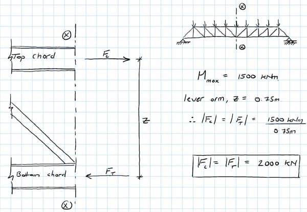
Quick hand calculation to determine max forces developed in the truss chords
Say a moment of is developed at the mid-span of a simply supported truss. We can solve for the axial force in the top and bottom chord by dividing the moment by the lever arm available, let’s say . In this case the lever arm is the distance between the centroid of the top and bottom chords. This will give an axial force magnitude in the top and bottom chords of . The forces that develop in the top and bottom chords form an internal couple (two parallel forces, equal magnitude & opposite direction) that resists the bending moment induced by externally applied loads.
Assuming that the compression case will dictate the size of both chords, we can simple spec a member that has a buckling resistance in excess of the axial load developed due to the bending moment we need to resist. The buckling capacity will be strongly dependent on the distance between lateral restraints. How the truss is restrained ‘out of plane’ is an important consideration not to overlook.
Determining the size of internal members is similarly straightforward once the magnitude of internal forces in each member has been determined. In most cases (statically determinate trusses) this can be readily achieved by carrying out a method of joints and or method of sections analysis. This analysis allows us to quickly scheme design a number of truss options in response to a particular design requirement.
Structural models versus real world behaviour
It’s important to understand some of the common assumptions that are often applied to truss analysis. In fact, these assumptions speak to a more fundamental point which applies to structural analysis generally and in particular ‘by-hand’ methods of analysis as-opposed to computer-based analysis.
The point is this…when we set about analysing a truss we first have to construct a model on which to base our analysis. That model might well be a line-diagram drawn on a page. But we always must remember that the model is an imperfect representation of the real world structure. It’s our approximation of the actual structure and will almost never capture 100% of the detail of the real-world structure.
Sometimes these differences between model and structure are quite small, in which case we can have more confidence in our analysis. However if we’re not careful the simplifying assumptions that facilitate our analysis can be so limiting that the model behaviour is not a good representation of the structure. Having an appreciation for the impact of how your assumptions degrade the accuracy of your model is crucially important.
Truss Analysis Assumptions
So, what assumptions apply to the analysis of trusses? The first one has already been mentioned; we assume that the nodes or joints that connect members behave as pins. In other words, if we consider two members meeting at a joint, they would be free to rotate relative to each other. Now, the implication of this is that no bending moments can be transmitted through a joint, only force.
This leads to the second assumption; the members within a truss are subject to axial loads only, tension, compression or no force. Provided all external loads are applied at joints, then no bending will be induced within any of the members. Of course if an external force was applied to a member between joints, normal stresses due to bending would be induced in that member, but we typical try to avoid this ‘inter-nodal’ loading in trusses if possible.
The obvious question is how valid are these assumptions? Well, regarding the pinned joints, in reality true pins allowing free rotation are very rarely provided. This is mainly driven by the relatively high cost of fabricating such joints. In a steel truss, the joints are almost always bolted or welded. As such, bending moments will be transmitted to some degree through joints and therefore within the structure.
However, the geometry of the joints is usually such that their ability to transmit moment is quite limited. So our assumption usually causes model behaviour to deviate relatively little from the actual structural behaviour. With reference to the members developing only axial loads, it follows from our discussion of joints, that if inter-nodal loading is minimised, the predominant action experienced by the members will be axial force. So, all-in-all our truss models, that we use to carry out method of sections and method of joints analysis on, are pretty reasonable approximations of real truss structures.
Dr Seán Carroll's latest courses.



Featured Tutorials and Guides
If you found this tutorial helpful, you might enjoy some of these other tutorials.
A primer on the form and behaviour of gridshell structures
The evolution of gridshells and techniques for form finding and analysis

Dr Seán Carroll
How I Coded an Analytical Beam Calculator
How I built my analytical beam calculator, beamsolver.com and the challenges I encountered along the way

Vittorio Lora
