Arch Analysis – How to Analyse Determinate and Indeterminate Arches
![[object Object]](/_next/image?url=%2Fimages%2Fauthors%2Fcallum_wilson.jpg&w=256&q=75)
Welcome to this tutorial on the arch analysis. Within this tutorial, we will develop an understanding and appreciation for the behaviour of arch structures as well as the techniques that can be used to analyse them.
Arch structures are found all over the world and many of these structures were designed and constructed hundreds of years before engineering theory, as we know it today, was developed. In many ways, arch structures represent one of the purest structural forms. By the end of this tutorial, you will be confident in explaining the behaviour of arches and conducting structural analysis on this fundamental and historic structural form.
All Access Membership
Learn, revise or refresh your knowledge and master engineering analysis and design
Access Every Course and Tool
- Over 1140 lectures & over 234 hours of HD video content
- Access member-only 'deep dive' tutorials
- Access all downloads, pdf guides & Python codes
- Access to the StructureWorks Blender addon + updates
- Packed development roadmap of courses & tutorials
- Price Guarantee – avoid future price rises as we grow
- Priority Q&A support
- Course completion certificates
- Early access to new courses
1.0 Why were arches a popular structural form in the past?
Construction materials such as steel and steel-reinforced concrete are relatively recent developments in engineering history. Ancient civilisations were able to construct incredible arch structures using materials far more primitive than those we take for granted today. How were they able to do this?
Well, either through trial and error or remarkable ingenuity, these historic structures relied on compressive axial stiffness rather than bending stiffness. By this, we mean that the structures worked predominantly in compression rather than in bending. Why is this important?
The primitive materials which were available before modern steel and RC, such as stone or early forms of un-reinforced concrete, exhibited high axial compressive stiffness. This made them fantastic materials to use in structures which depended on high axial stiffness! The Romans didn’t need steel because their arch structures didn’t want to bend!
You might be asking why we no longer see huge stone arch bridges or viaducts being constructed in society today?
This is a good question….and in reality, the answer comes down to structural self-weight. Modern construction materials such as reinforced concrete exhibit exceptional axial stiffness and bending stiffness at a fraction of the self-weight of their ancient material counterparts. Therefore, nowadays, we are happy for our structures to resist loads through a combination of axial and flexural stiffness because modern materials allow both top be developed.
2.0 Classification of arches
Within this tutorial, we will consider three types of arch and present a different analysis method for each. We can think of these three arch types as the bounding cases for all the possible boundary conditions a real arch structure possesses. The three types are:
- Three-hinged Arch
- Two-Hinged Arch
- Fixed Arch
3.0 Geometric description of arches
Before we embark on our study of the three arch types and arch analysis generally, we need to equip ourselves with the tools to describe the geometry of an arch discretely. What do I mean by this?
When we analyse a horizontal beam, we are working in one dimension only, usually denoted as the axis. We don’t need to worry about the axis because all points on the beam have a y-coordinate, .
Arches are two-dimensional structures. The value of changes for every value of .
In horizontal beams, the distribution of internal forces (bending moment, shear forces and axial forces) are described in terms of the variable . It should be no surprise, therefore, that the internal forces in an arch are described in terms of and .
We must, therefore, be able to describe the shape of our arch structures before we consider analysing the internal forces.
Within this tutorial, we will consider the two most common arch geometries:
- The Circular Arch
- The Parabolic Arch
3.1 Circular Arch
Consider the below circular arch:
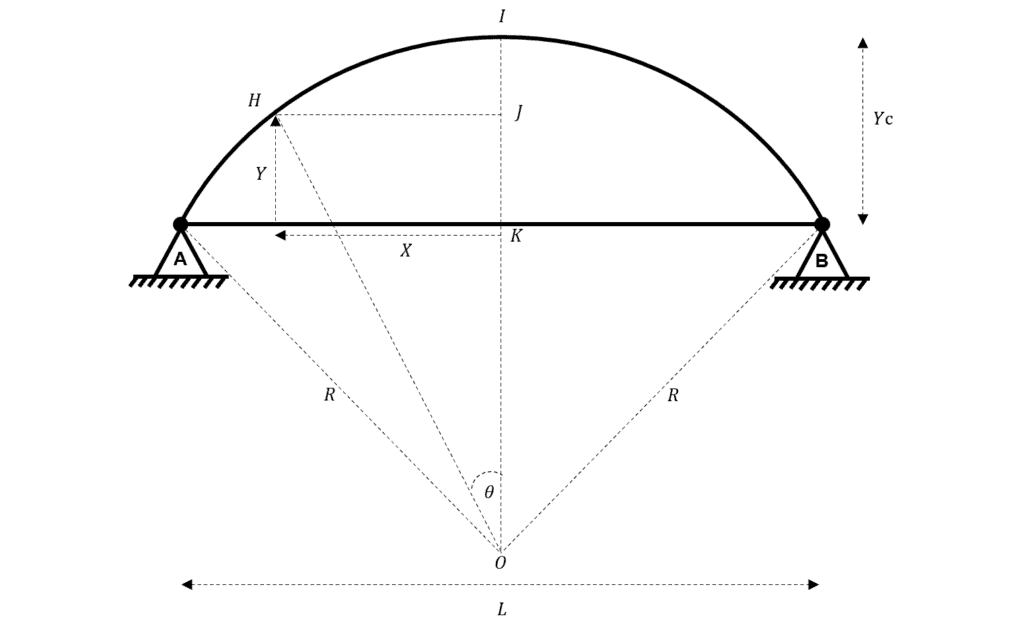
Fig 1. Circular arch geometry.
is the radius of the circle at centre of which the arc is a part of.
is the rise of the arch.
is measured from the origin outwards.
is measured from the horizontal line defined by .
Consider triangle OEF
3.2 Parabolic Arch
Consider the following parabolic arch:
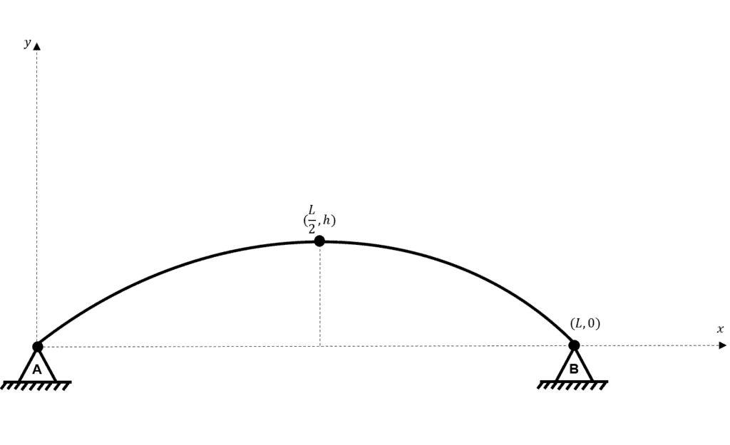
Fig 2. Parabolic arch geometry.
For any concave parabola with vertex at , the general form of the descriptive equation is:
where is some constant
Now consider a parabolic arch with vertex , the general equation describing the arch is:
To determine the constant we utilise either of our boundary condition points; or .
At :
Now, we have determined the value of the constant we can revisit the general form.
4.0 Three-Hinged Arch
We start our exploration of arch analysis by considering the simplest form of the arch. The three-hinged arch has three hinges in its profile. There is a hinge at each support and an additional hinge on the centre line of the arch at its maximum rise, known as the crown.
Immediately, we can infer that a three-hinged arch has three points which cannot support a bending moment i.e. . This will be important when we come to form our equations of equilibrium.
For now, let us set up an example problem. We will consider a three-hinged arch subject to a uniformly distributed load (UDL) over its projected length.
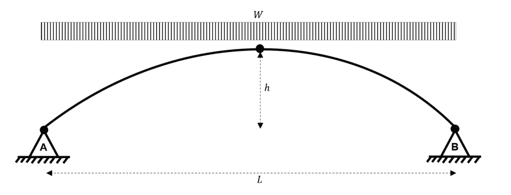
Fig 3. Three-hinged parabolic arch subject to a UDL.
Initially, an arch problem can appear daunting due to the curved profile of the element. However, even for arch problems, we should start by considering static equilibrium to calculate the reactions.
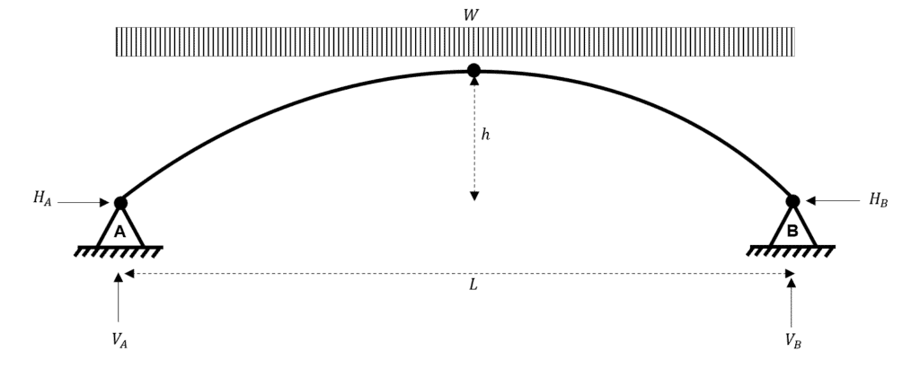
Fig 4. Reactions for the three-hinged parabolic arch subject to a UDL.
What is the first thing that jumps out to you?!
For me, arches are a peculiar structural form because, for static equilibrium to be met, we must satisfy two horizontal reactions (known as thrust reactions) even though there is no horizontal/inclined loading. This should indicate to you how load is carried within an arch……more on this later!
Now, as usual, we proceed to consider the static equilibrium of the structure. We have four unknown reactions to determine….ask yourself whether this structure is determinate or indeterminate.
First, we consider vertical equilibrium.
Now we consider horizontal equilibrium.
This result is not particularly useful, and we could have reached this conclusion without any equations!
What’s our next move….well we should think about which other equilibrium equations we have available…
First, let us consider moment equilibrium about point A.
This is what we would expect, but it doesn’t help us to determine our final two unknown reactions ( and ).
So let us instead consider a moment equilibrium equation, considering the influence of the forces acting to the left of the central hinge; after all, we have said that this is a point where .
So now that we have determined our four unknown reactions, we can re-draw the structure.
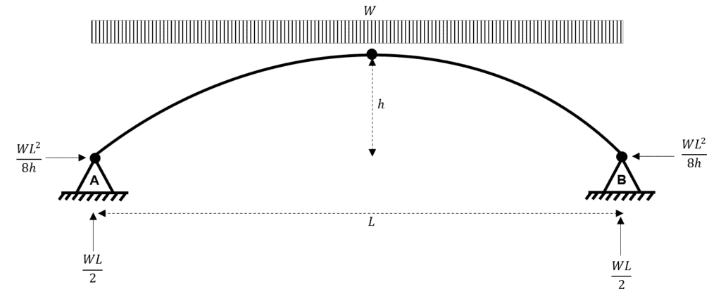
Fig 5. Calculated reactions for the three-hinged parabolic arch subject to a UDL.
As normal, once we have determined all of the unknown reactions, we can consider the profile of internal forces
Let us say that we now want to obtain the internal forces at some point with coordinates , measured from an origin at point A.
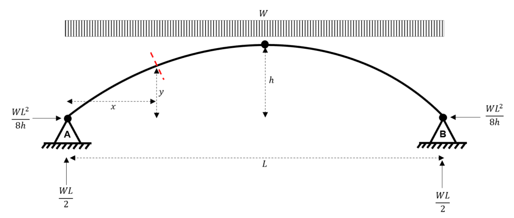
Fig 6. Choosing the position for our slice through the arch.
We go about determining the internal forces in the same way that we do for any simple beam; we make a cut at the location of interest.
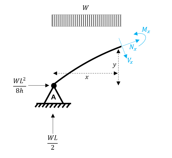
Fig 7. Taking equilibrium about the exposed edge.
Let us first consider moment equilibrium at the exposed cut.
Notice that we have a y-variable within this expression, which is not much use to us as we are trying to express the distribution of bending moments in terms of the position along the arch i.e. along the x-axis.
To solve this problem, we refer back to our earlier consideration of arch geometries. In this problem, we are considering a parabolic arch, and we have already established a description of this type of arch.
So we simply substitute this description for ‘y in terms of x’ into our equation of moment equilibrium above.
Since we generalised the equation by expressing moment equilibrium in terms of , we can say that the result i.e. is true for any position on the arch.
We have shown that the value of the bending moment at any position is equal to zero. I find this to be an interesting result and one that isn’t immediately obvious when we first approach the problem.
For the vertical shear we can use a simple statics result to determine the distribution of radial shear forces. Don’t be concerned by the term ‘radial’…this simply means shear force which is normal to the tangent of the arch at any point. For a horizontal beam (which we are typically concerned with), the radial shear equals the vertical shear!
Since
and we know that for all , we can say that for all too!
If you would like to prove this result in a different way, why not try and establish a vertical force equilibrium at any cut along the arch.
And finally, for the normal force .
is simply the resultant of and .
And what do we notice about this expression for ? that’s right, it is a constant i.e. it does not contain the variable term . is also negative, which indicates that this is a compressive axial force.
Having concluded this example, let us reflect on our findings.
We can say that for a parabolic-shaped three-hinge arch subject to a UDL along its full projected length:
- the bending moment at all is zero
- the shear at all is zero
- the normal force which acts tangentially to the arch at all is a negative and constant value which represents uniform axial compression
So, our arch structure experiences a vertical distributed load (much in the same way that a horizontal beam does) but does not experience any bending moments or shear forces along its length. Instead, load transfer between the arch and the supports occurs via pure axial compression.
As an exercise, try some alternative imposed load cases on our three-hinged arch. You could apply a UDL to just half the projected length of the arch or perhaps apply a single point load at a discrete location. You can utilise the exact same procedure as we did above for any combination of imposed loads.
You will discover that the parabolic arch with UDL is a unique case! For other load cases, there will be non-zero bending moments and shear forces along the length of the arch. If you are interested in learning about other structures which exhibit this ‘moment-less’ behaviour, they are referred to as funicular forms and represent perhaps the most efficient structural forms available! A hanging cable, also known as a catenary, is also a funicular form. You can learn more about the analysis of cables in this EngineeringSkills course.
Modelling and Analysis of Non-linear Cablenet Structures using Python and Blender
Learn how to combine parametric modelling, exploratory form-finding and iterative analysis techniques to simulate 3D tensile structures.
After completing this course...
- You will be able to apply an iterative Newton-Raphson technique to solve for the non-linear behaviour of 3D cablenet structures.
- You will be able to apply parametric modelling and simulation-based form finding techniques to generate cablenet geometry.
- You will have developed a complete modelling, analysis and visualisation workflow for exploring these elegant yet complex structures.
So, referring back to our very first consideration of historic arch structures…..what shape do you think the Romans constructed their arches, given that their available building materials had low bending stiffness? I’ll leave that to you to ponder 🙂
5.0 Two-Hinged Arch
Now we can move on to two-hinged arch analysis. To keep things simple, we will consider the same arch geometry as the three-hinged arch – a parabolic arch.
All we need to do is remove the hinge from the centre point or crown of the arch. This is a simple modification in principle, but it has a major consequence on how we analyse the arch.
First, let’s draw our arch with its unknown reactions.
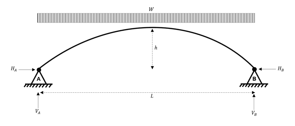
Fig 8. Two-hinged parabolic arch subject to a UDL.
The number of reactions is the same as for the three-hinged arch, four. However, you may already have spotted the problem. Unlike with the three-hinged arch, we only have three equations of equilibrium. This means that the two-hinged arch is statically indeterminate to the first degree.
The indeterminacy of the two-hinged arch is the major difference compared to the three-hinged arch.
Ok, so where do we go from here?
Which structural analysis techniques do we have for analysing indeterminate structures? Perhaps the most common (and versatile) is the direct stiffness method…would this be suitable for analysing arches?
Yes, we could approximate the behaviour of the arch quite well using the direct stiffness method. However, we would need to approximate the geometry of the arch by a series of straight-line ‘beam’ segments. The direct stiffness method is a ‘node-based’ analysis method, which means it cannot capture or represent (directly) anything about the geometry of the structure between nodes and hence it cannot capture the curvature of the arch – it can only approximate it. If we discretise the arch into sufficiently short line segments, our approximation can, in fact, be excellent.
However, in this tutorial, which focuses on the theory of arches, we’ll focus on a method which captures the theoretical behaviour of the arch. To do this, we direct our attention to our old friend, the virtual work method. We’ve covered virtual work extensively in previous tutorial, e.g. here, and in multiple courses, here, here and here.
We set the problem up as follows. We need to define a statically determinate system (the released system) and a compatible reactant system. The sum of the released system and the reactant system yields the real system.

Fig 9. Summary of the virtual work system.
In general, we can say:
We should note that the reactant system is multiplied by to acknowledge that we need the magnitude of the reaction to be scaled from a value of to .
As usual, we construct our expression of virtual work by considering the internal work and external work executed by our system.
For the external work:
By compatibility, we know that should be equal to zero, therefore:
for the internal work, we use the general description for strain energy due to bending
where is the real system and is the virtual system
However, we have already stated that , and therefore:
Now equate the external work to the internal work
Great, we now have an expression for horizontal force …are we finished?
Not quite…can you spot any issues?
Firstly, we know that virtual work equations should be integrated over the length of an element i.e. the sum of all . However, we typically express the geometry of an arch in terms of the horizontal and vertical axes. Therefore, we now need to re-write our expression for but with the integral variable replaced by .
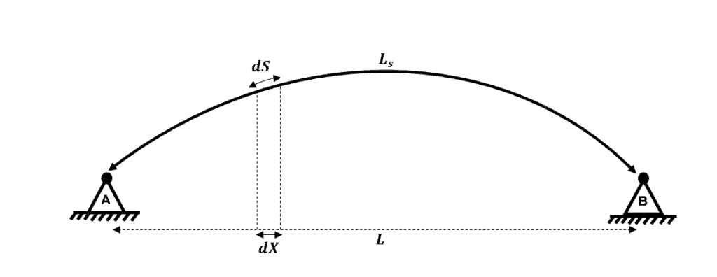
Fig 10. Changing the integration variable.
We want to transform our integral limits from to
First, we define as the angle between and , therefore:
and from this, we can simply say that
Therefore
Now this is a tricky integral to solve analytically and we would prefer if we could remove the terms. However, because the terms are themselves functions of the variable we cannot simply cancel across the two integrals…is there something else we could do which would allow us to cancel the within the integrals?
Yes! For an arch, we normally assume that where I is the moment of inertia of the arch at any position on the element and is the moment of inertia of the arch at the crown; therefore,
Now, this probably doesn’t look like a very simple equation for us to use but in the following worked example, you will see that this equation is really not too complex to implement!
Now we are going to work through the example of a UDL applied to the entire span of a two-hinged parabolic arch.
Let us recall the equation which we need to determine , the unknown reaction in this 1st order indeterminate system
We begin by considering
Next, we consider
Our current expression for also includes the variable. This makes the solution of the integral more complicated, and we would prefer to have the expression for written in terms of only. Therefore, we need to replace in our expression with using the parabolic arch equation we defined at the start of this tutorial.
Therefore, considering the upper term in our expression for
Next, we move onto the lower term in our expression for
Now we return to evaluate our expression for
Wow! This is exactly the same expression as for the three-hinged arch!
What about the bending moment in the arch? Will this be the same as the three-hinged arch case?
We have said that:
which gives us
which simplifies to
So yes, the bending moment distribution is the same for the two-hinged arch as it is for the three-hinged arch i.e. the bending moment is zero at all locations in the arch. By inspection, this also means that the radial shear force is also zero at all points.
As for the axial force in the arch, the vertical reaction at and is the same as the three-hinged arch and is the same so therefore will be the same as for the three-hinged arch case.
6.0 Fixed Arch
The final type of arch we will consider is the fixed arch. The fixed arch is indeterminate to the third degree, but importantly, we can use essentially the same method we used in our two-hinged arch analysis.
Again, we will consider a parabolic arch subjected to a UDL across its full projection.
Because we have three redundant reactions, we define the following system. Using the same logic as for the two-hinged arch, we replace the real system with a released system (determinate) and three reactant systems. For this example, we have three reactant systems because the real system is indeterminate to the third degree.
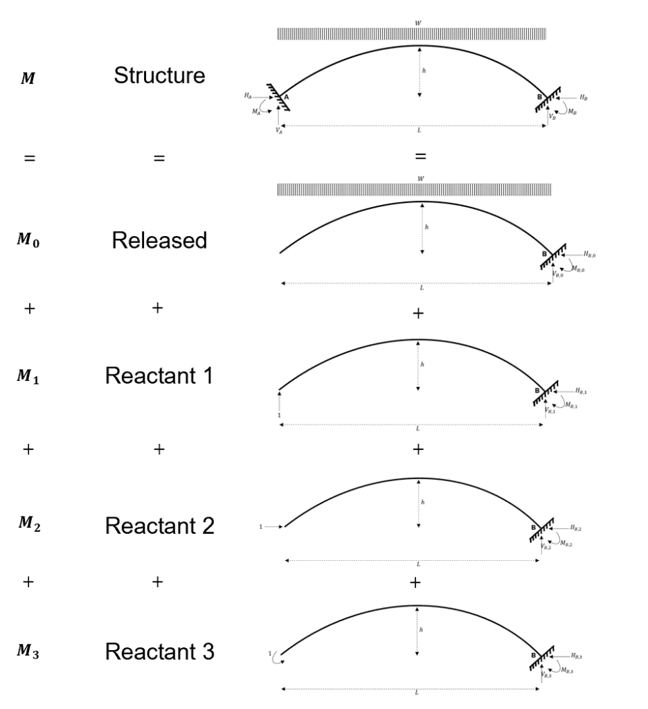
Fig 11. Summary of the virtual work system.
From which we can say that.
Again, we note that each of the reactant systems is scaled by its corresponding redundant reaction.
For each of the three redundant reactions, we construct our virtual work relationship whereby we consider the equilibrium of internal and external work.
First we consider
For the external work:
By compatibility we know that should be equal to zero, therefore:
for the internal work, we use the general description for strain energy due to bending
But recall that
therefore,
therefore
Next we consider
For the external work:
By compatibility we know that should be equal to zero, therefore:
for the internal work, we use the general description for strain energy due to bending
But recall that
therefore,
therefore,
And finally, we consider
For the external work:
By compatibility, we know that should be equal to zero, therefore:
for the internal work, we use the general description for strain energy due to bending
But recall that
therefore,
therefore,
We can simplify these expressions by considering expressions for , , and
For , we can consider the released system as a simple cantilever and hence
We can also use our previous integral substitution to replace with and to remove the terms by replacing with .
Re-writing our three expressions:
So in fact, we now have a set of three simultaneous equations with three unknowns, , and . We now solve the integrals within each expression and simplify the results as much as possible.
You can follow the manipulation of the algebra if you choose to, but the above expressions simplify down to:
which, when solved simultaneously, yields
Wow, that was an awful lot of algebra to obtain exactly the same results as we did for the three-hinged and two-hinged arches! In the next section, we will think about the results for all three of our arch problems.
7.0 Thinking about our Results
We have analysed a parabolic arch subject to a UDL over its full projection. We have considered three distinctive sets of boundary conditions: three-hinged, two-hinged and fixed.
The three-hinged arch was statically determinate so we were able to use simple equations of static equilibrium to solve this problem.
The two-hinged and fixed arches were statically indeterminate and we employed the virtual work method and displacement compatibility relationships to determine the redundant reactions.
So what did we find?
We found that for all three sets of boundary conditions, the reaction forces and the moment/shear/normal force distribution were identical. This is an important finding and we should think about this a little further!
To put this finding into context, think about whether this would be the case if we were analysing a horizontal beam. If we compared a horizontal beam with pinned supports subject to a UDL to a horizontal beam with fixed supports subject to the same UDL, would we expect to see identical bending moment and shear force distributions?….of course not! The internal force distribution would be drastically different between these two cases.
At the start of this tutorial, we reflected on the importance of arches as a historic structural form and hopefully, you are now beginning to understand why they were so prevalent. Put simply, provided that an arch is constructed in a parabolic shape, and that the loads applied to the arch are uniform and that either pinned or fixed support conditions are achieved, the arch will carry the load in pure compression. No bending moment, no shear forces and hence the ability to use simple construction materials such as stone, bricks or early un-reinforced concretes.
8.0 Arch Geometry and Loading
To keep things manageable in this tutorial, we have considered one specific arch geometry and one specific set of applied loads. As discussed, the case we have considered is ‘special’ in that a UDL applied to a parabolic arch results in an arch which transfers loads in pure compression.
So, what happens if we change the arch geometry?
If we change the arch geometry from parabolic to circular (or to some parametric from in between), the manner by which the arch transfers load will change. Importantly, however, regardless of the geometry of the arch, the analysis techniques used in the above three examples can be employed.
Providing that the arch geometry can be described in as a function of and , the analysis process is the same, except for a slightly different expression for in terms of (and some slightly more involved algebra and trigonometry).
So what happens if we change the applied loads?
If we change the applied loads, then we will also observe a change in the way that the arch transfers this load. Again, regardless of the set of applied loads (UDL, concentrated loads etc), the analysis process does not change.
For the three-hinged arch, changing the applied loads will not pose a problem as we can account for any load in our consideration of equilibrium. For the two-hinged and fixed arches, we account for the applied loads in our expression for and therefore, provided that we can develop an expression for which accounts for the applied loads, then we can use the same analysis techniques as per the examples in this tutorial.
This should give you the confidence to go and analyse any arch geometry, subject to any set of applied loads and under any set of boundary conditions!
9.0 Arch Support Stiffness
For the case of statically determinate arches, you now have all of the tools to go and analyse different arches. As usual, however, we quickly come to the conclusion that real arches are almost certainly not statically determinate!
Real arches are statically indeterminate and during our analyses, we have assigned either two-hinged or fixed boundary conditions to the problem. Are these theoretical boundary conditions a good representation for what we would expect in reality? Can we be confident that this idealised theoretical behaviour is a good model for the behaviour of a real arch?
Let’s consider the two-hinged case:
A hinge support (sometimes called a pinned support) must provide a vertical and horizontal reaction. Hinge supports do not need to (and cannot) provide a moment reaction.
In general, we can be happy that the vertical reaction of an idealised hinge support can be realised in practice. We know that with appropriate foundations and ground conditions, we can develop extremely large vertical reactions to resist the vertical force at the hinge support.
What about the horizontal reaction?
Within our analysis, we have assumed that the full horizontal reaction can be developed at the hinge support. This means that the support has infinite stiffness, and hence under the applied reaction force , the associated displacement is taken to be zero. We know that, in reality, it is not possible to achieve .
So, how could we quantify the finite stiffness of the horizontal resistance of the hinge support. As part of a hand analysis, a simple analogy for horizontal support stiffness can be drawn by considering a tied arch.
We haven’t talked about tied arches within this tutorial yet, but they are a common type of arch used in bridge engineering. The reason they are popular is that the horizontal stiffness of the support is determined solely by the axial stiffness of the tie element. The tie connects the hinge supports at either end of the arch and works in tension to resist the outwards thrust which is present at each of the hinge supports.
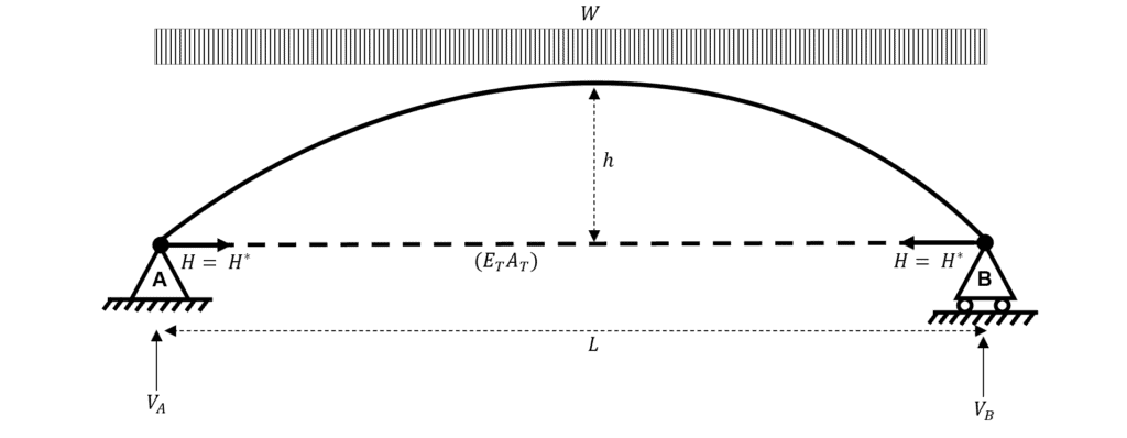
Fig 12. Two-hinged tied arch subject to a UDL.
Consider a simple example which is directly comparable with the ‘un-tied’ two-hinged arch case we considered in the worked example above.
We let be the tension in the horizontal tie (which is equal to the thrust at either of the hinge supports).
From the above expression, it can be seen that for any realistic value of , the denominator of the expression will be and hence will be less than the horizontal reaction which we assumed when analysing the un-tied arch. So what?
Well, if the horizontal reaction is reduced from to , and we reconsider the moment equilibrium at the crown of the two-hinged arch, we find the following:
We see that there is now a sagging bending moment at the crown of the arch, when previously there was zero bending moment at the crown (and everywhere else)!
This simple example demonstrates that the realistic horizontal stiffness of the supports (which we have modelled using a tie element) has a significant role on the internal force distribution of the arch. We have proved that if the horizontal reaction is reduced due to the support stiffness, then the bending moment at the arch crown becomes non-zero. Note that if you consider the above equation for , then the perfect theoretical case is only obtained if ….which we know is not possible in reality.
10.0 Arch Member Axial Stiffness
We have to consider one final topic to make sure we are considering the real behaviour of arches. In the three examples which we have studied, it was shown that the arch transferred the applied load to the supports via pure compression. Even with realistic support stiffnesses, arches predominantly develop compression in response to external loading. With this in mind, we have to consider the axial stiffness of the arch element itself.
To simplify our consideration of the axial stiffness of the arch element we will revert back to assuming that the hinge support can form an ideal horizontal reaction. In reality we would have to consider the interface between the stiffness of the support and the stiffness of the element itself. We will leave this type of analysis to the computers!
Accounting for the axial deformation of an arch is rather simple and just requires us to modify our expression for . Again, we will denote as the modified expression for the horizontal reaction.
In the general case:
So, what can we observe from this expression?
For the case of a UDL applied over the full projection of the arch, we know that and hence the term on the numerator of the above expression can be removed.
Now, from this expression, we can see that as the axial deformation increases i.e. the increases, the magnitude of decreases…..interesting!
We assess the consequence of this reduced horizontal reaction by considering moment equilibrium about the crown of the arch.
This tells us that when the axial stiffness of an arch is considered, there must always be a non-zero bending moment at the crown of the arch. As before, the perfect theoretical case is only achieved when goes to ….which we know is impossible.
With that said, the axial stiffness of arch structures is typically very large and hence for a first approximation, the axial deformation terms are generally omitted from the expression for .
11.0 Conclusion
That brings us to the end of this tutorial on arch analysis. I hope you enjoyed it as much as I enjoyed writing it!
As a recap, we have covered:
-
Why arch structures are such a common structural form, particularly historically.
-
We formulated expressions for both parabolic and circular arches.
-
We developed arch analysis methods for determinate and indeterminate arch structures subject to uniformly distributed loads.
-
We identified how theoretical simplifications which we make during the analysis have significant effects on the distribution of internal forces.
-
We developed more advanced expressions of displacement equilibrium, which account for support stiffnesses and arch element axial stiffnesses.
Arches are a fantastically efficient structural form which is why we see so many examples from all periods across the history of engineering. We have just scratched the surface with regards to the analysis of arches and I encourage you to try out some of your own arch problems using the techniques covered in this tutorial.
Thanks for exploring arch analysis with me! If you enjoyed this tutorial and found it helpful, why not recommend it to a friend?
See you in the next one!
Featured Tutorials and Guides
If you found this tutorial helpful, you might enjoy some of these other tutorials.
Yielding, Plastic Deformation and Moment Redistribution in Beams (2/2)
Learn how calculate plastic moment capacities and how moment redistribution occurs in a structure

Dr Seán Carroll
Code, Context, and Calculation - A Modern Framework for Engineering
Building reliable and auditable systems with Python and AI

James O'Reilly


