Strength Design of Singly-Reinforced Concrete Beams using ACI 318-14
![[object Object]](/_next/image?url=%2Fimages%2Fauthors%2Fdan_ki.png&w=256&q=75)
In this tutorial, Dan Ki is back to guide us through the flexural and shear design of reinforced concrete sections using ACI 318-14. This tutorial is a great starting point for anyone looking to learn the basics of reinforced concrete design from a US perspective. If you want to read a Eurocode version of this tutorial, check out this tutorial or our course on Reinforced Concrete Design to Eurocode 2.
Fundamentals of Reinforced Concrete Design to Eurocode 2
An introduction to ultimate limit state design for bending and shear with optional calculation automation using Python.
After completing this course...
- You will be able to determine design actions using the Eurocodes Basis of Structural Design (EC0) and Actions on Structures (EC1).
- You will understand balanced section design and how to analyse and safely design singly and doubly reinforced concrete sections.
- You will understand how to apply the Variable Strut Inclination Method for shear reinforcement design.
- You will have developed your own reinforced concrete design codes in Python (the Python pathway is optional in this course).
Enjoy the tutorial!

In this tutorial, we will go over the basics of concrete beam analysis and design. Specifically, we will go over the strength design of singly reinforced members.
We will limit our discussion to rectangular sections. However, once the theory is covered for this section shape, you should find it simple enough to extrapolate to various other cross-sectional shapes.
1.0 American Concrete Institute - ACI 318-14
The 2014 version of ACI 318 went through a major reorganisation from its previous versions. Though the transition was frustrating at first, I've come to find that it is more logically organised than its previous versions. ACI 318-14 comprises of 10 general parts:
- Part 1: General
- Part 2: Loads & Analysis
- Part 3: Members
- Part 4: Joints/Connections/Anchors
- Part 5: Earthquake Resistance
- Part 6: Materials & Durability
- Part 7: Strength & Serviceability
- Part 8: Reinforcement
- Part 9: Construction
- Part 10: Evaluation
Navigating this newly organised code is as simple as referencing the member to be designed, and that chapter will, for the most part, reference all the other chapters needed to design the member. Our focus today will be Chapter 9: Beams (in Part 3) and Chapter 22: Sectional Strength (in Part 7).
2.0 Reinforced concrete (in a nutshell)
A reinforced concrete beam relies on a somewhat complex interaction between the concrete and the reinforcing steel embedded within it. Reinforced concrete beams are essentially composite beams, with each material serving a different purpose. In this section, we’ll briefly review how we characterise the flexural and shear capacity when designing reinforced concrete beams.
2.1 Flexure of a singly reinforced member
Concrete is essentially just an engineered rock. As you may intuit, "rocks" are fairly weak in tension, but are excellent at carrying compression. In a flexural concrete section, reinforcing bars (aka rebar) are added to the tension zone and the concrete itself is assumed to resist zero tension.
ACI 318-14 22.2.2.2: Tensile strength of concrete shall be neglected in flexural and axial strength calculations.
In this manner, the reinforced concrete section takes advantage of the best qualities of both materials (concrete in compression and steel in tension). For a typical gravity load resisting beam, we place the reinforcement in the bottom face of the member - a singly reinforced beam. This is in contrast to a beam with reinforcement in the compression zone (top face) in addition to the bottom face - a doubly reinforced beam. We will discuss why we might want to add compression steel in a follow-up to this tutorial. For now, let's focus our attention on singly reinforced sections, Fig 1.
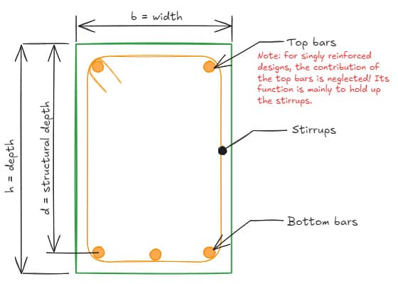
Fig 1. A singly reinforced concrete beam cross-section.
Below is a typical stress-strain diagram for concrete for a singly reinforced section.
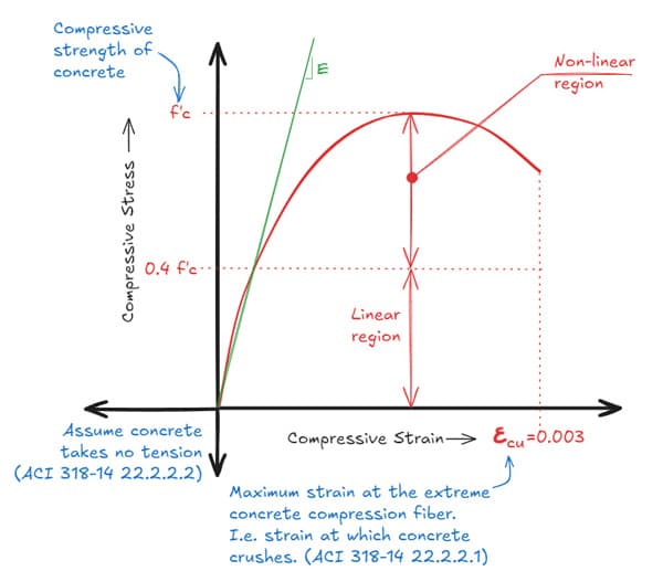
Fig 2. Typical stress-strain curve for concrete.
The Young's Modulus (E) is measured at times the peak compressive strength and the concrete is assumed to crush at a strain of .
ACI 318-14 22.2.2.1: Maximum strain at the extreme concrete compression fiber shall be assumed to equal to 0.003.
Thus, we are able to apply elastic beam theory up to , but how can we get to the ultimate capacity in the non-linear regime? If we knew the equation of the parabola, we could integrate it to get the area under the curve, which would give us the compressive stress.
However, it turns out that the shape of the parabola depends on . Extensive experimentation offers us a method to convert the parabolic stress distribution to an equivalent rectangular stress block, also known as the "Whitney Stress Block". Below is a graphical representation of ACI 318-14 Section 22.2.2.4.
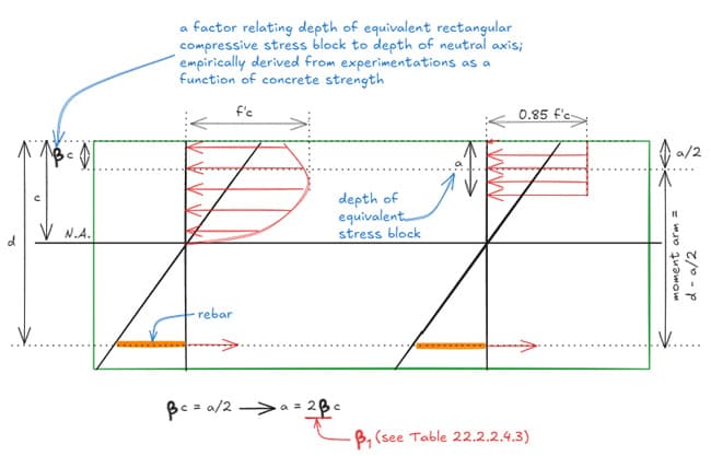
Fig 3. Parabolic and equivalent rectangular stress block.
Where is given by Table 22.2.2.4.3:
![Table 1. Values of $\beta_1$ for equivalent rectangular concrete stress distribution (Table 22.2.2.4.3 in [1]) | EngineeringSkills.com](/_next/image?url=%2Fimages%2Fposts%2Fstrength-design-of-singly-reinforced-concrete-beams-using-aci-318-14%2Fimg4.jpg&w=1080&q=75)
Table 1. Values of for equivalent rectangular concrete stress distribution. (Table 22.2.2.4.3 in [1]).
We now have everything we need to apply our static equilibrium equations for calculating flexural capacity:
- Compression in the concrete must equal the tension in the rebar.
- Nominal internal moment = (Tension Force) * (Moment arm).
2.2 Shear
The important concept in shear design is to know that external shear translates to internal tension in the concrete section.
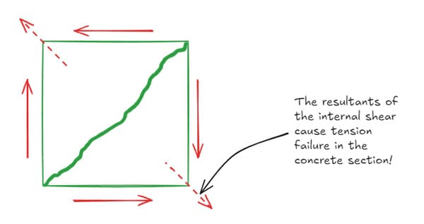
Fig 4. Shear stresses and the corresponding tensile stress.
While plain concrete does have some inherent shear capacity, most of the shear capacity comes from shear reinforcement.
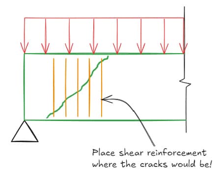
Fig 5. Typical placement of vertical shear links near beam supports.
In summary, shear capacity is the sum of:
- Concrete capacity,
- Shear reinforcement,
If you'd like a more in-depth tutorial of the concepts and theory, I would highly recommend reading this tutorial on the properties of concrete and this tutorial on the design of reinforced concrete before moving on.
3.0 Case study: Analysis
To get started, let's analyse a concrete beam using ACI 318-14 to familiarise ourselves with the Code. Then, we will move onto some design examples. Also, if you haven't committed the rebar diameters and areas to memory yet (🤓), refer to Appendix A - Steel Reinforcement Information:
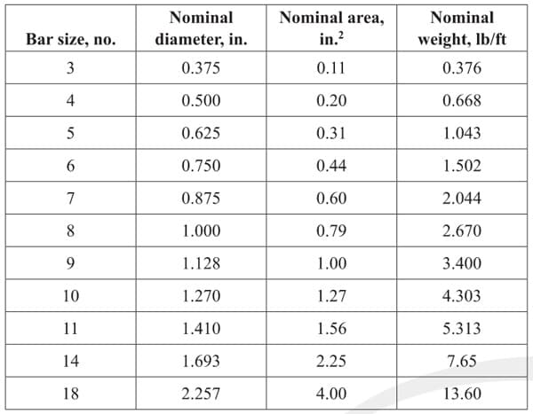
Table 2. Steel reinforcement information.
Say it's your first week on the job and you've been asked to check the strength of an existing concrete beam as shown below, Fig 6. Since this is an existing beam, we will assume that it is code-compliant. This may be a typical task in a renovation project where existing structural drawings are not available, if the reserve capacity of an existing beam must be calculated, or in a structural peer review, etc.
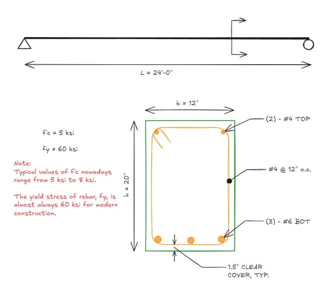
Fig 6. Concrete beam analysis example.
3.1 Flexure, Calculate
Where,
Use static equilibrium to calculate depth of equivalent stress block, a.
Thus,
To calculate the appropriate strength reduction factor for flexure, , we turn to Table 21.2.1 - Strength reduction factors .
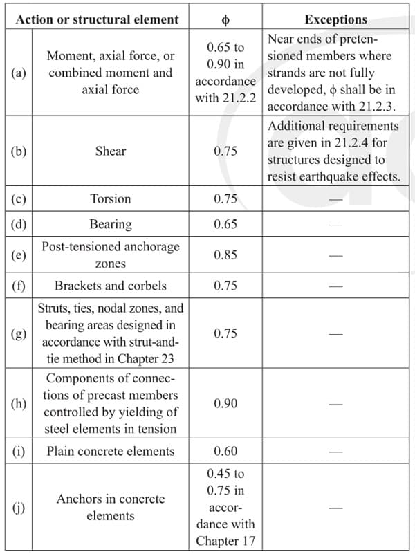
Table 3. Strength reduction factors (Table 21.2.1 in [1]).
It can be seen that varies depending on the strain in the steel, per Table 21.2.2 - Strength reduction factor for moment, axial force, or combined moment and axial force.

Table 4. Strength reduction factor for moment, axial force or combined moment and axial force (Table 21.2.2 in [1]).
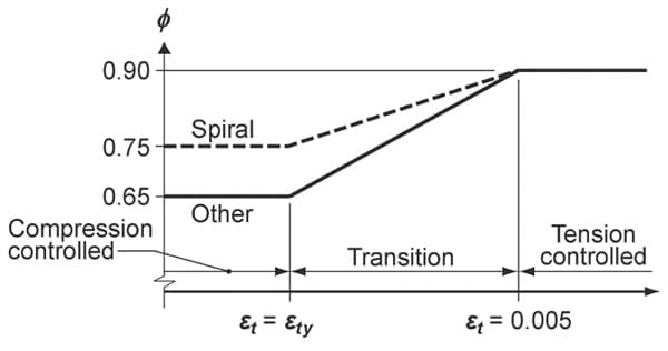
Fig 7. Variation of with net tensile strain in extreme tension reinforcement, . [1]
Note that in order to use the highest reduction factor (), we want our beams to be tension-controlled. In general, we want to stay in the tension-controlled region when designing beams!
In other words, we want the steel to yield before the concrete crushes. This is because a failure due to yielding of the steel is much more ductile than a concrete crushing failure, which happens suddenly and without much warning.
Let's calculate by similar triangles.
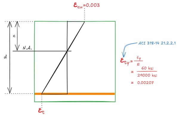
Fig 8. Calculation of using similar triangles.
Recall from Figure 3 that . Hence,
Thus,
Finally, we can determine our flexural capacity!
3.2 Shear, Calculate
You'll find that ACI 318 provides a bit more guidance on calculating shear capacities of concrete beams. Let's dive right in.
ACI 318-14 22.5.1.1: Nominal one-way shear strength at a section, shall be calculated by:
The commentary in the same section notes that "shear strength is based on an average shear stress over the effective cross section, ", where is the width of the web and is the effective (or structural) depth.
To calculate the concrete's contribution to shear resistance, we turn to section 22.5.5.1.
ACI 318-14 22.5.5.1: For nonprestressed members without axial force, shall be calculated by: unless a more detailed calculation is made in accordance with Table 22.5.5.1.
is a lightweight concrete reduction factor. For normal weight concrete, .
Feel free to check out Table 22.5.5.1, but I will say from experience that it is common practice to just use . The accompanying commentary also notes that "for most designs, it is convenient to... use equal to as permitted in Eq. (22.5.5.1)."
Note that should be in units of psi, and that the units of are, strangely, also in units of psi. This nonhomogeneous expression of taking the square root of is common in ACI 318; it is empirically derived and aligns well with experimentation.
ACI 318-14 22.5.10.1 stipulates that shear reinforcement shall be provided to make up the difference in demand and the resistance provided by the concrete section. i.e.
where is given by ACI 318-14 22.5.10.5.3 as
where,
- = the area of steel resisting shear (i.e. the area of the stirrups)
- = spacing of the stirrups
So in sum, we finally have our equation to calculate the nominal shear capacity of our beam:
As we saw before in Table 21.2.1 (Table 3 above), for shear. Thus,
Awesome, we've analysed our first beam! Truth be told, analysis is straightforward and is much simpler than a design problem. When tasked with designing, there are an infinite set of solutions, and it is important for an engineer to come up with an efficient and elegant design. Let's see how we can get there in the next section.
4.0 Case study: Design
Design is solving the opposite problem of analysis. As previously stated, there are an infinite set of designs that can satisfy a problem. In this section, we will discuss some of the below design considerations in the context of economy, constructability, and architectural constraints:
- How to proportion a beam
- How to reinforce a beam
- Should we have more rebar with lower or fewer, larger diameter bars?
- How should we space our shear reinforcement?
- When should we use doubly-reinforced beams?
- Choosing the right .
Let's tackle this, again, in the context of a task you might receive in a design office. Say your supervisor asks you to find a design for 2 simply supported beams, TB01 ("TB" referring to "Transfer Beam") and FB01 ("FB" referring to "Floor Beam"), Fig 9.
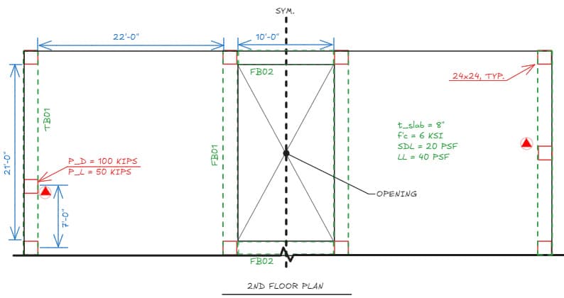
Fig 9. Design example plan layout.
4.1 Floor beam design - FB01
As always, let's start by finding our demands:
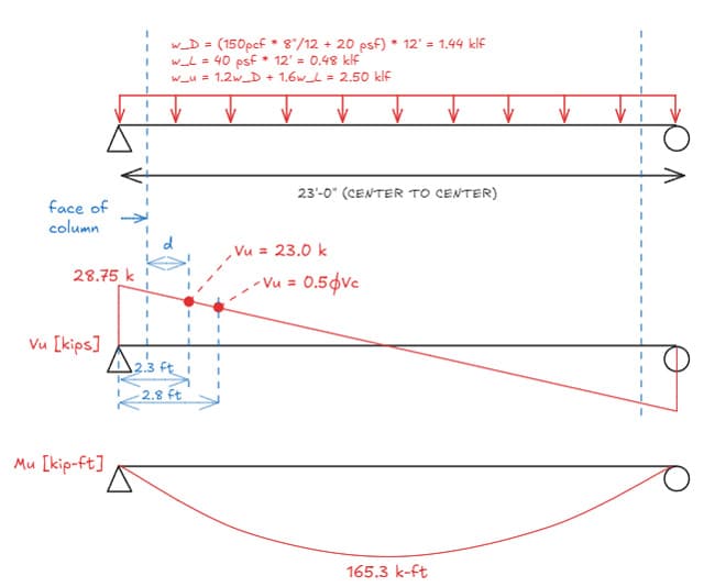
Fig 10. Floor beam 01 (FB01) general arrangement and loading.
Now that we have our demands, how do we size the beam? From a practical perspective, here are some initial constraints to consider:
-
Try to match the width of the beam to the width of the supporting columns. This is a constructability consideration; if the width of the beam matches the width of the column, then the formwork will align nicely between the two elements, generally resulting in lower formwork and labour costs.
-
Try to limit the maximum depth of the beam to the topside of the architectural soffit. Refer to the architect's reflected ceiling plans! If a beam needs to be deeper, then be sure to let the architect know and coordinate the design.
For our example, let's assume the floor-to-floor height is and the architectural soffit in this area is at from top of slab below, giving us a maximum depth of (or ).
As for the minimum depth, let's turn to ACI 318-14 9.3.1.1:
![Minimum depth of nonprestressed beams (Table 9.3.1.1 in [1]) | EngineeringSkills.com](/_next/image?url=%2Fimages%2Fposts%2Fstrength-design-of-singly-reinforced-concrete-beams-using-aci-318-14%2Fimg15.jpg&w=1200&q=75)
Table 4. Minimum depth of nonprestressed beams (Table 9.3.1.1 in [1])
From Table 9.3.1.1, we can see that our minimum depth is . It is typical to use even numbered beam sizes, so let's try a wide deep beam.
4.1.1 Flexure
To find the limits of our flexural reinforcement, let's again turn to ACI 318-14.
*ACI 318-14 9.6.1.1: A minimum area of flexural reinforcement, shall be provided at every section where tension reinforcement is required by analysis.
is provided in the following section (9.6.1.2) as: The only unknown is the effective depth, . At this point you may have noticed we are in a bit of a chicken and egg situation. How can we know our effective depth when we have not sized the stirrups or the flexural reinforcement?
This is where an engineer's experience can help, but to be frank, it is a trial and error process (and this is also the same process that most commercial software uses as well!). For a singly reinforced beam with one layer of reinforcement, a common starting point is to take as .
Which in our case, will be:
The following are valid for min. steel (in theory).
| Count | Rebar Size | Bar Spacing [clear] | |
|---|---|---|---|
| 12 | #3 | 1.32 | 1.4" |
| 7 | #4 | 1.4 | 2.75" |
| 4 | #5 | 1.24 | 5.8" |
| 3 | #6 or #7 | 1.32 / 1.8 | 8.9" / 8.7" |
| 2 | #8 or #9 | 1.58 / 2.0 | 18" / 17.7" |
| 1 | #10 | 1.27 | - |
Engineering judgement plays a big part in deciding which of these designs might be the most suitable. A #3 or #4 bar is not commonly used as longitudinal reinforcement in beams because they are easily bent out of place when stepped on in the field. One should also consider that more bars in a beam implies more labour.
Now there is a matter of bar spacing permitted by ACI 318. For minimum spacing, Section 25.2.1 specifies that _"For parallel nonprestressed reinforcement in a horizontal layer, clear spacing shall be at least the greater of 1 in., , and ."_
Maximum bar spacing is generally a serviceability issue to control flexural cracking; the Commentary R24.3.1 says that "Improved crack control is obtained where the reinforcement is well distributed over the zone of maximum concrete tension. Several bars at moderate spacing are much more effective in controlling cracking than one or two larger bars of equivalent area." Table 24.3.2 provides the maximum permissible spacing in beams:
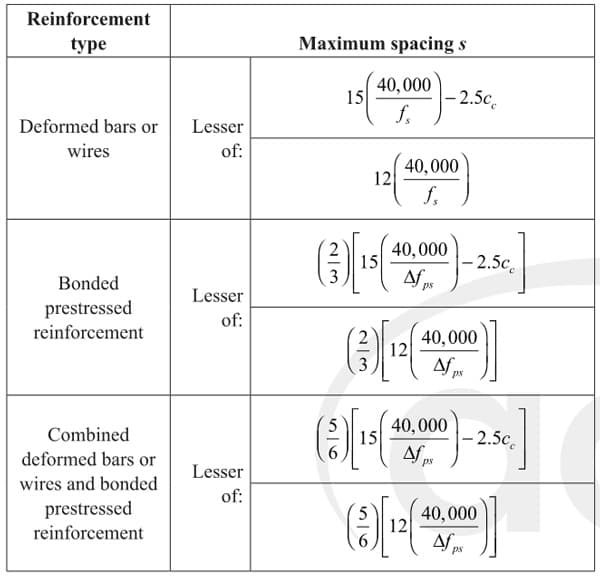
Table 5. Maximum spacing of bonded reinforcement in nonprestressed and Class C prestressed one-way slab and beams (Table 24.3.2 in [1])
is the clear cover to the longitudinal bar and is the rebar tensile stress at service loads and is allowed by Section 24.3.2.1 to be taken as .
So assuming aggregate, our maximum spacing is:
Given that this is a simple floor beam with a reasonable span, let's try to make this work with a #6 longitudinal bar and #4 stirrups.
Where,
Use static equilibrium to calculate depth of equivalent stress block, a.
Thus,
Solving the quadratic above, we see that we need (6) - #6 bars. Before we verify that does indeed = 0.9, let's digress a little to look at our design from a different perspective.
So far, we've been working with the same equations as in our analysis example, but for design, it can often be convenient to rearrange the equations to be in terms of reinforcement ratio, . Then, from above can be expressed as:
The benefit of doing this is that we have removed the dimensional variables; as long as we provide the minimum reinforcement ratio, we know that our design will be code-compliant for the required lower bound reinforcement.
How about for the upper bound? As discussed above, we want to use the maximum reduction factor of . i.e. when .
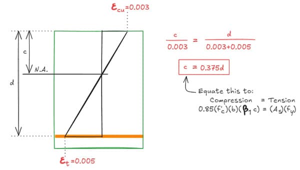
Fig 11. Strain distribution.
So we have,
For a 6 ksi beam reinforced with 60 ksi rebar, the maximum reinforcement ratio in order to use is 2.4%.
Now going back to our example, in lieu of calculating the strain in the steel, let's see if we are tension-controlled based on reinforcement ratio.
We can see that the reinforcement we provided falls between and , so we are able to use !
4.1.2 Shear
Per ACI 318-14 9.4.3.2, is permitted to be taken at d away from the face of support. Let's see how much capacity we can get from our gross concrete section:
Looks like our concrete section is more than adequate, but as in flexural design, ACI 318-14 9.6.3 stipulates minimum shear reinforcement:
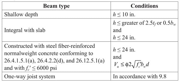
Table 6. Cases where is not required if (Table 9.6.3.1 in [1]).
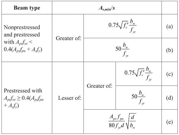
Table 7. Required (Table 9.6.3.3 in [1]).
So per code, we need:
Since we are governed by minimum shear reinforcement, we can use the maximum stirrup spacing permitted by the code, which is , as given by Table 9.7.6.2.2:
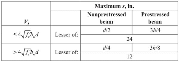
Table 8. Maximum spacing of shear reinforcement (Table 9.7.6.2.2 in [1]).
This brings us to a final shear reinforcement of:
We can use (2) - #3 stirrups, one placed at and one placed at (per our shear diagram). While this is a code-compliant solution, it is likely not the final design that will appear on the structural drawings.
4.1.3 Final Design
To aid in constructability and to minimize contractor errors, it is common to extend the minimum stirrups throughout the beam. The final design may look something like the below:
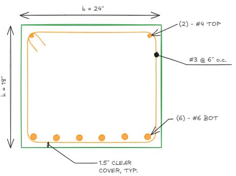
Fig 12. FB01 Final design.
Before we move onto the final example, let's take a short breather and recap what we've done. As you can see, beam design often is an iterative process with many things to consider.
For our flexural design, we saw that our reinforcement ratio was far below , so we could have used a shallower beam, but then we would have had to re-check our reinforcement as well. We certainly could have used a smaller beam width, but we decided to match the column width for ease of construction. We also added (2) - #4 top bars that were not used in our calculations to help hold up the stirrups in the field.
Given this iterative and repetitive nature, I would highly recommend creating a program to quickly do these calculations. The simplest implementation would be an Excel spreadsheet that calculates flexural and shear capacities with perhaps a few code checks for minimum areas of steel, spacing requirements, etc. I personally like to use PyNite to calculate the demands, coupled with an office spreadsheet that calculates capacities.
Among all of these design variables, the one that we haven't considered adjusting was . Determining is generally set in the early stages of a project and is almost always governed by what is required for the columns and shear walls. If you have a 40-story building, the columns at the base will likely require a higher than those of a 10-story building.
In addition, the column is commonly reduced towards the top of the building, where there is less gravity load and overturning moments from lateral loads.
Once is determined for the columns, the corresponding beam and slab strength can be determined. Without going into too much detail, it is common for the slabs/beams to either have the same strength as the columns or (See Section 15.3.1 to learn why).
As a last point on concrete strength, it is considered good practice to use as few design mixes as possible, usually a maximum of 2 different strengths per floor.
4.2 Transfer beam design - TB01
In this example, we are to design a transfer beam, TB01. As always, we determine our design forces and moments, Fig 13.
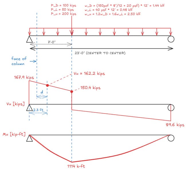
Fig 13. Transfer beam 01 (TB01) general arrangement and loading.
4.2.1 Flexure
Recall that for 6 ksi concrete and 60 ksi rebar, and . For a first approximation, let's take a weighted average 60% of and 40% of :
Let's now re-write our moment equation in terms of :
We can now solve for :
Let's try a beam using #10 rebar:
While you might be tempted to stop here, we again need to stop and think about the spacing of the longitudinal bars. Will (9) - #10 bars fit in a wide beam?
At this point, we could either split the reinforcement into two layers, or we can increase our beam depth. Let's increase our beam depth to assuming 1 layer of (8) - #10 rebar:
Now to finally verify our flexural capacity:
4.2.2 Shear
Recall that total shear resistance is the addition of concrete's shear resistance and shear resistance provided by the stirrups:
As before, let's start by calculating concrete's shear resistance, :
Now, the balance must come from stirrups:
A #3 stirrup with max spacing of provides . You may have noticed that the shear varies along the length of the beam, so in theory, we could have varied our stirrup reinforcement.
It is common for a beam to have regions where substantial shear reinforcement is required and regions where minimum reinforcement or no reinforcement is required per code, but in practice, shear reinforcement is rarely varied throughout the length of the beam.
Again the logic here is to minimise the chance of an error in the field, especially when it comes to shear failures. It is common practice to calculate the reinforcement required at the critical section and apply it everywhere.
Lastly, it is my personal preference to reinforce beams with longitudinal bars larger than a #9 with at least a #4 stirrup. This is because the stirrups act to hold the longitudinal bars in place before concrete is cast, so a slightly "beefier" stirrup will help the longitudinal bars to not sag between the rebar chairs and maintain adequate cover.
So in sum, our design will come down to something like:
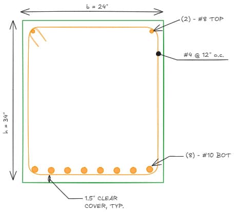
Fig 14. TB01 Final design.
5.0 Design quick tip
If you'd like to quickly check if a beam's design is roughly in the ballpark of being adequate, I'd like to introduce this handy trick: Note that is in units of kip-ft, and is in units of inches. This equation is not dimensionally consistent! This "equation" is exact for and , and is convenient to quickly spot check designs.
If we apply this to our first example,
Dividing this by the area of a #6 bar,
Pretty close to our final design of (6)-#6 bars!
Let's try again on TB01:
Dividing this by the area of a #6 bar,
Again, pretty close! This trick also comes in handy as an excellent starting point in your design if the dimensions of the beam is known.
6.0 Beam design summary
In this tutorial, we've worked through a few examples of sectional strength design of beams using ACI 318-14. Here's a handy graphical representation of our design process:
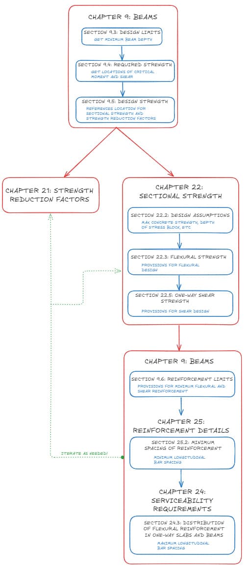
Fig 15. Beam design flow chart.
The beams we've designed today are adequate for strength, but we have not considered deflection. In the concrete design tutorial, we will dive into deflection of concrete beams and the important role that compression reinforcement plays in controlling long term deflection while also providing some additional moment capacity. See you in the next one!
Featured Tutorials and Guides
If you found this tutorial helpful, you might enjoy some of these other tutorials.
Bonsai BIM - The Essential IFC Tool for Structural Engineering Workflows
The IFC tool every structural engineer should have in their toolkit

Petru Conduraru
Parametric Graphic Statics with GeoGebra
Increase the precision and speed of your analyses with parametric graphic statics.

Prof Edmond Saliklis
Understanding Structural Dynamics and Inertia
How and why dynamic analysis is performed instead of simpler static analysis

Dr Seán Carroll


