Beam Design using the American Institute of Steel Construction (AISC) Manual
![[object Object]](/_next/image?url=%2Fimages%2Fauthors%2Fdan_ki.png&w=256&q=75)
In this tutorial, Dan Ki is going to walk us through the design of a steel beam using the American Institute of Steel Construction (AISC) Steel Construction Manual.
This is our first design tutorial that uses the AISC Steel Construction Manual and our first non-Eurocode design tutorial. Considering the large readership EngineeringSkills has in the US, I'm hoping that we can publish many more non-Eurocode tutorials and design guides in the future.
So, if you're one of our US-based readers (or you just happen to use non-Eurocode design guides) and would like to contribute to EngineeringSkills, we're especially keen to hear from you. Get in touch here.
If you're looking for the Eurocode version of this beam design tutorial, you'll find that here.
Now, over to Dan!

As a new structural engineer, one of the first tasks you might receive will likely be to design a beam. Beam design is a task structural engineers will regularly perform, and as such, it is important to learn how to design them efficiently and gain proficiency.
One of the other goals of this tutorial is to get you comfortable navigating the AISC Manual. This tutorial will also provide a light refresher on the basic beam limit states.
1. The AISC (American Institute of Steel Construction) Manual
The AISC Steel Construction Manual (the Manual) is a performance-based standard that has evolved and developed since its first publication in 1927 in an effort to codify and standardise steel design. The Manual is the de facto standard for steel design in the US and is adopted by all national and local building codes (and some international building codes).
Navigating the Manual
Though technically comprised of 17 Parts, the Manual can broadly be thought of as being composed of 3 general sections:
- Parts 1-15: References, requirements, and guides for the design of various structural steel members, components, and systems.
- Part 16: Specifications and Codes:
- Specification for Structural Steel Buildings, AISC 360-10 (the Specs)
- Specification for Structural Joints Using High-Strength Bolts (RCSC)
- Code of Standard Practice for Steel Buildings, AISC 303-10
- Part 17: Miscellaneous Data and Mathematical Information
Our discussion today will be limited to the design of non-composite beams under uniaxial flexure and will focus on Parts 1-3 of the Manual and Chapters F and G of the Specs.
We also assume a basic knowledge of the elastic and plastic theory of beams. If you need a quick refresher, refer to The Stress-Strain Curve & Plastic Hinges in Beams (1/2)
2. Flexural Design
2.1 Theory
Beam design is broadly a function of...
- Material properties
- Geometric properties (, compactness, etc.)
- Quick note - the symbols adopted by AISC for , , and differ from those used by Eurocode 3, so we will explicitly define them here to avoid confusion.
- - Second moment of area, a.k.a. moment of inertia
- - Elastic section modulus
- - Plastic section modulus
- Strong axis bending is about x-x
- Weak axis bending is about y-y
- Torsion is about z-z
- Quick note - the symbols adopted by AISC for , , and differ from those used by Eurocode 3, so we will explicitly define them here to avoid confusion.
- Unbraced length of beam,
- Loading condition ()
There are numerous limit states that can apply to beams. To help contain the discussion, we will cover the most common ones. However, for an exhaustive list, see Table User Note F1.1.
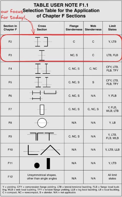
Fig 1. Table User Note F1.1
Below are the limit states we will discuss.
Strength Limit States:
- Flexural yielding (Plastic Hinging)
- Inelastic lateral-torsional buckling
- Elastic lateral-torsional buckling
- Shear yielding
Serviceability Limit States:
- Deflection
- (Vibration & fatigue are some other examples of serviceability limit states, but are outside the scope of this tutorial)
All of the flexural design provisions may be found in Chapter F of the Specs. AISC treats all flexural limit states with the same capacity reduction factor, (LRFD) and safety factor (ASD). We will use the LRFD method of strength design in this tutorial.
Shear provisions are found in Chapter G of the Specs. The resistance factor for shear, , is for all members except for "stockier" webs of I-shaped members, for which per Specs Section G2.1(a). We will expand on this later.
Material and Geometric Properties
Modern steel beam design assumes an idealised elastic-perfectly-plastic material response, meaning that the governing constitutive relation in the elastic regime is Hooke's Law, and the ultimate flexural capacity of the beam can be developed at a member's plastic limit, .
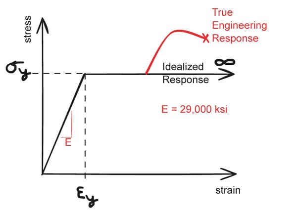
Fig 2. Idealised elastic-perfectly-plastic material response for steel.
is calculated by Spec Eqn. F2-1 as:
where = yield stress of steel, () and = plastic section modulus about the x-axis, . In order for a member to achieve this plastic capacity, it must be compact and adequately braced.
Compactness (a cross-section limit state)
Flexural "compactness" refers to a cross-section's ability to receive compressive strains in the plastic regime prior to local buckling. For a given material, it is purely a function of the geometric proportions of a cross-section. In essence, if a member is to achieve its plastic capacity, its constituent parts must be "stocky" enough to not buckle prior to yielding.
See Chapter B Table 4.1b for compression element members subject to flexure.
Per User Note in Spec Section F2,
All current ASTM A6 W, S, M, C, and MC shapes except W21x48, W14x99, W14x90, W12x65, W10x12, W8x31, W8x10, W6x15, W6x9, W6x8.5 and M4x6 have compact flanges for ; all current ASTM A6 W, S, M, HP, C and MC shapes have compact webs at .
Practically speaking, given that a vast majority of beams have compact flanges, I generally tend to avoid choosing to design with non-compact or slender cross sections where possible.
In summary, if any portion of the cross-section is not compact (i.e. non-compact or slender), it will not exhibit sufficient ability to rotate at its hinge, and thus will not be able to develop its full plastic capacity.
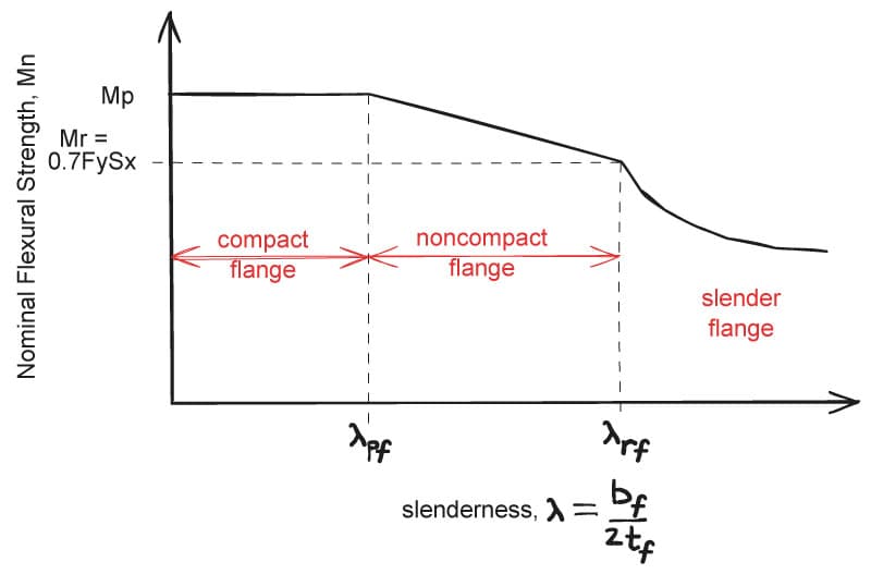
Fig 3. Normalised flexural strength versus slenderness.
See Table B4.1b of the Specs for criteria to determine and .
What does it mean for a beam to be "adequately braced"? (a member limit state)
As mentioned above, for a beam to achieve its plastic capacity, it must be adequately braced in addition to being compact. According to AISC Appendix 6.3,
Beam bracing must control twist of the section, but need not prevent lateral displacement.
A useful mental model when thinking about beam limit states is to break the beam up into constituent plates that make up the member (e.g. think of a wide flange beam as being made up of 3 plates).
Consider a simply supported I-beam with a uniformly distributed load, which puts the top flange in compression and the bottom flange in tension. Now, it is easy to see that an unbraced top flange would tend to buckle as though it were an axially loaded Euler column.
If the beam is sufficiently unbraced, it will be subject to a common strength limit state called "lateral-torsional buckling", or "LTB" for short. Lateral-torsional buckling refers to the tendency of a beam's compression flange to buckle out of plane (i.e. laterally) while being partially restrained by the stabilising force of the tension flange, causing twist (i.e. torsion). Lateral-torsional buckling does not apply to flexural members bent about their weak axis or HSS bent about either axis, per AISC Specifications Sections F6, F7, and F8.
While we won't go into a derivation of the elastic lateral-torsional buckling equations, it is helpful to understand some underlying assumptions to gain an intuition.
Assumptions:
- material remains linear-elastic
- plane sections remain plane (negligible shear deformations)
- deformations are small (small angle theory is employed)
- major axis moment of inertia is much greater than minor axis moment of inertia (i.e., )
- beam is loaded with a constant moment along its length
Based on these assumptions, the elastic lateral-torsional buckling equation boils down to Specs Eqn. F2-4 as:
where,
- = LTB modification factor (we'll get into this later, but for now think of it as a coefficient )
- = unbraced length of the beam, .
- = torsional constant of cross section, (Tabulated in Manual Table 1-1)
- = warping constant of cross section, (Tabulated in Manual Table 1-1)
- = distance between flange centroids, in. (Tabulated in Manual Table 1-1)
- = effective radius of gyration for the determination of LTB, (Tabulated in Manual Table 1-1)
- = a shape-based coefficient; for a doubly symmetric I-shape,
Rather cryptic, right? Through the many editions of AISC, this equation has been rearranged and "simplified" to a point where the terms in the equation have lost all meaning.
Again, a full derivation is beyond the scope of this guide, but let's "un-rearrange" this back to a form that is closer to its originally derived (and equivalent) form to see if we can make better sense of what is happening:
Ok, I'll be the first to admit that this this isn't much better, but we did lose some made-up variables in the process. Let's see if we can extract some meaning from this.
Firstly, we have and , which tells us that we are in some kind of elastic regime. Next, if we take the term out of the square root, we get , which smells like a buckling equation. The term, , should alert us to the fact that St. Venant's torsion is being baked in, and lastly, the term points to some sort of warping torsion.
Without having to derive and solve a scary fourth order differential equation, we were still able to somewhat gain an intuition to how the elastic LTB equation might work. That's a win in my book!
So now that we have tackled plastic yielding and elastic LTB, you may wonder if there is a whole other equation to calculate inelastic LTB. Clearly, elastic LTB is only applicable for loads that do not yield the cross section. Thankfully, AISC approaches inelastic LTB using linear interpolation between the two limit states, and . The below figure depicts the 3 regimes of flexure as a function of the unbraced beam length, .
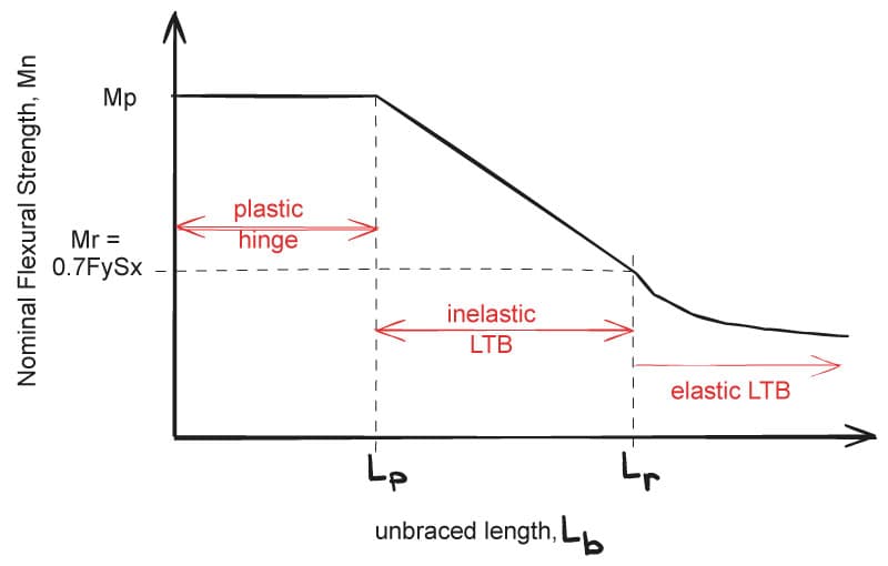
Fig 4. Three regimes of flexure as a function of the unbraced beam length, .
Where: is the limiting laterally unbraced length for the limit state of yielding and is given by,
and is the limiting unbraced length for the limit state of inelastic LTB and given by,
The moment , is simply the moment at yield accounting for the inevitable residual stresses in the beam during its hot-rolled fabrication process. It can be seen that AISC assumes a reduction to to account for this. Thus, in the inelastic LTB regime,
Up to this point, we have provided equations of LTB based on the assumption that the beam is loaded with constant moment along its length, but what if the beam has a different loading configuration? This is where the lateral-torsional buckling modification factor, , comes into play.
, The Moment Gradient Coefficient
For non-uniform moment diagrams, (also referred to as the "moment gradient coefficient") is an amplification factor to the nominal moment, , but must at all times be less than and is defined as:
where is the absolute value of maximum moment in the unbraced segment, and , , and are absolute values of the moments at quarter, half, and three-quarter points of the unbraced segments, respectively.
The big idea behind the factor is to exploit the fact that less heavily loaded adjacent beam sections effectively "brace" critical sections at incipient LTB.
Put another way, amplifies the moment capacity to account for more favourable loading conditions to the worst case constant moment loading assumption from which it is derived.
This has the following effect on the curve:
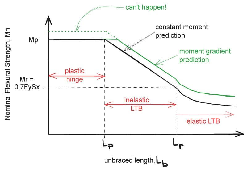
Fig 5. Three regimes of flexure as a function of the unbraced beam length, accounting for the moment gradient coefficient,
For common values of , see AISC Table 3-1.
With the theory covered, we are almost ready to put it all together to design our first beam! Keep the above table (Fig 1) handy as a summary of flexural design.
3. Design of Members for Shear
AISC, unlike some other codes, treats shear independently from flexure. Per Specs Chapter G Commentary,
Consideration of shear and bending interaction is not required because the shear and flexural resistances can be calculated with a sufficient margin of safety without considering this effect.
AISC also only considers the web of I-shaped members to resist shear forces. As such, the nominal shear strength, is given in Specs Eqn. G2-1 as:
where,
- = yield stress of the member,
- = area of the web, (full depth of member thickness of web)
- = web shear strength coefficient
, also known as the post-buckling strength reduction factor, as the name suggests, accounts for the reduction in strength in the case that the cross section's web buckles prior to yielding. for a vast majority of available wide flange beams, but for detailed criteria, refer to Specs Chapter G2.1(b).
Section 4: Steel Beam Design - Putting it All Together
Let's finally get our hands dirty with some examples! The three examples provided will cover common loading configurations, so hopefully you'll be able to derive some useful design heuristics for your own practice.
We will use both the Spec equations and the handy tables in Part 3 of the Manual. In addition, we will attempt to put our examples into the context of "design" as a whole. Thus, we will also touch on various design considerations and how they might affect the final designs.
Example 1 - Filler Beam Design
Design a long filler beam spaced on center with the following loading criteria:
- DL = ( Light Weight Concrete on Metal Deck)
- SDL = (finishes, partitions, etc.)
- LL = (office)

Fig 6. Beam design example 1
We start by evaluating the design moment and shear in the beam:
So we now have our design moment and shear, great. Now what is the unbraced length of our beam? Recall that our problem statement indicated that the beam supports a concrete on metal deck. In practice, this indicates a type of continuous (or near continuous) bracing since the concrete on metal deck is stiff enough to prevent twist of the top (compression) flange. Thus, we can take . Or, if you'd like, you can safely take to be the distance between the flutes of the deck, typically .
Since we know that we can take advantage of the full plastic capacity, our problem reduces to:
Great, so long as we choose a beam with a , we're golden, but what size will give us the most efficient design? This is where the Manual Table 3-2 comes into play.
In Table 3-2, "W-shapes are sorted in descending order by major axis flexural strength and then grouped in ascending order by weight with the lightest W-shape in each range in bold. is taken as unity" (emphasis mine).
Based on this table, a W16x31 is the lightest shape that meets the requirement.
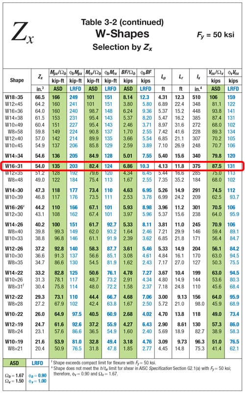
Fig 7. Table 3-2, The American Institute of Steel Construction Manual.
Notice that this table also provides , which is greater than our , confirming our assumption that we can design to the plastic limit. Notice also that the shear capacity is provided, but let's check it manually once:
For a W16x31:
Now that our strength checks are done, we should check deflection, which is a serviceability limit state. We didn't cover this yet, but IBC (International Building Code) defines deflection limits as such:
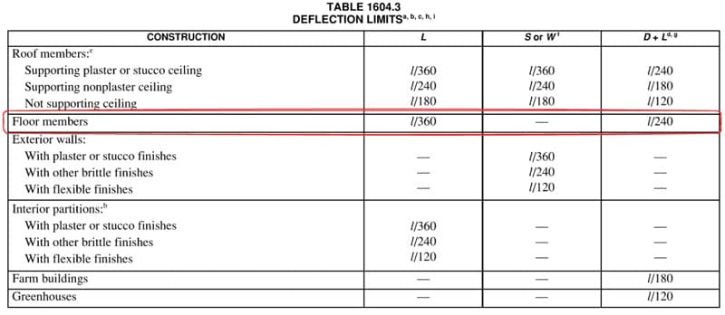
Fig 8. International Building Code deflection limits.
Let's quickly check the deflection of our beam (by the way, Manual Table 3-23 provides common moment, shear, and deflection equations for beams of common loading and boundary conditions):
Let's now solve for required .
Going back to Table 3-2, it appears that a W18x40 is the lightest section that meets the minimum moment of inertia. Always remember to check deflection as it may control the design!
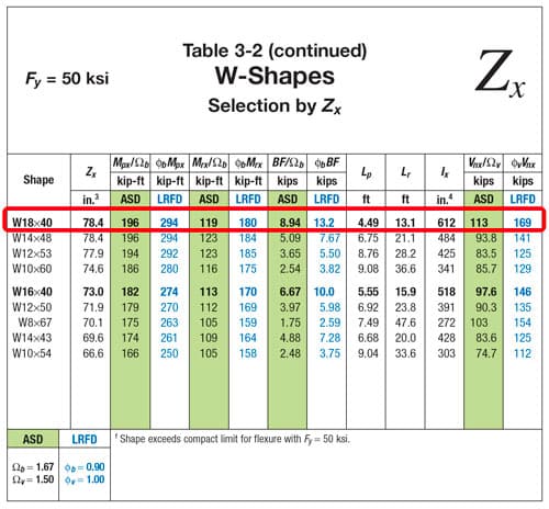
Fig 9. Table 3-2, The American Institute of Steel Construction Manual.
Example 2: Roof Girder Analysis
Check an existing W18x50 roof girder with the loads shown below.
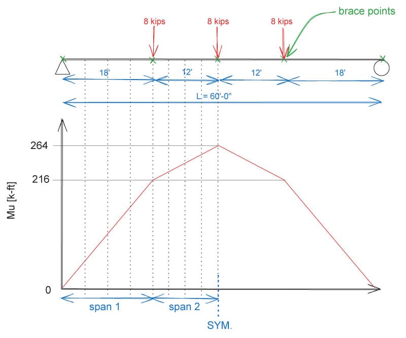
Fig 10. Beam design example 2.
To find for the unbraced lengths, we can use Specs Eqn F2-2 and F2-3, or we can use Manual Table 3-10, which graphs available moment vs. unbraced lengths. Note that Table 3-10 uses !
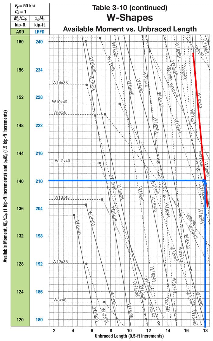
Fig 11. Table 3-10, available moment versus unbraced length, The American Institute of Steel Construction Manual.
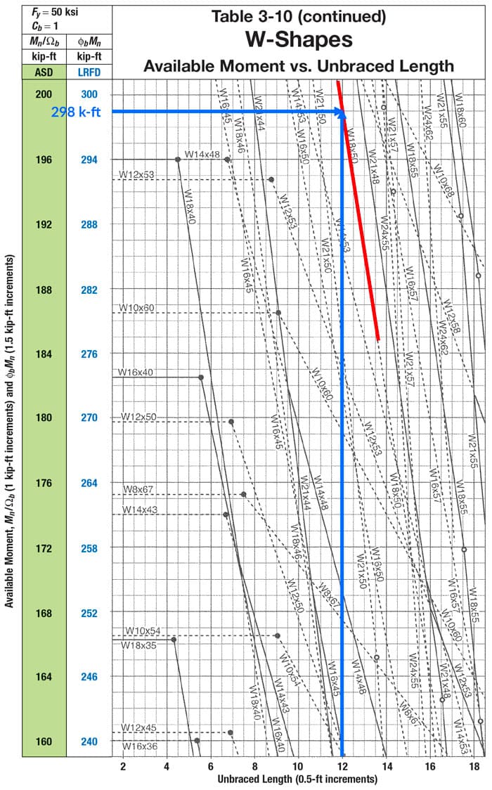
Fig 12. Table 3-10, available moment versus unbraced length, The American Institute of Steel Construction Manual.
Now, tabulating the final results (noting the symmetry about the midpoint):
| Spans 1 & 4 | Spans 2 & 3 | |
|---|---|---|
| 18' | 12' | |
| 216 k-ft | 264 k-ft | |
| 210 k-ft | 298 k-ft | |
| 1.67 | 1.05 | |
| 351 k-ft | 313 k-ft | |
| 379 k-ft | 379 k-ft | |
| ? | OK | OK |
Note that for spans 1 and 4, the beam would be inadequate without . It's easy (and conservative) to not include the moment gradient coefficient, but it can make a big difference in the capacity. Notice that we get a 67% boost for spans 1 and 4! The steeper the moment gradient (i.e. the slope of the moment diagram for a given unbraced span), the larger will be. Recall that for a constant moment gradient, .
Example 3: Transfer Beam Design
Design a transfer beam with the same distributed loads as Example 1, but with a point load as shown below.

Fig 13. Beam design example 3
The design moment and shear are obtained as follows:
Similar to example 1, since we are nearly continuously braced, we can take . Going back to Table 3-2, we find that a W36x135 is the lightest section that satisfies the flexural and shear demands.
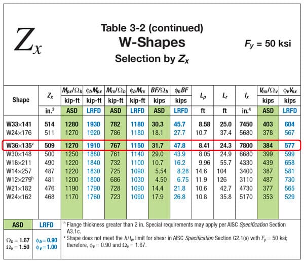
Fig 14. Table 3-2, The American Institute of Steel Construction Manual.
Using superposition of deflections for a uniformly distributed load and for a concentrated load for a simple beam, it can be seen that the maximum deflection occurs at approximately from the left side of the beam.
Feel free to verify this yourself either by hand or using software. Let's now check this against our allowable deflections per IBC.
In example 1, we saw that the design was governed by deflection, but due to the large point load in this example, the design is governed by flexure.
These types of conditions happen often where a column transfers its load to a beam below. In early design phases, it is generally ok to size the beams for just moment, shear, and deflection. However, as the design progresses, one must also consider the effect of the concentrated loads on the flange and web of the beam. While beyond the scope of this tutorial, Specs Chapter J10 addresses these additional limit states.
4. Tips and Tricks
Once you've designed a few beams by hand, you'll start to develop an intuition as to what "seems right" or is in the general ballpark. In this section, we will lay out some tips and tricks as well as some things to consider when selecting a beam.
-
A normally loaded floor beam's depth will roughly be half of the span in inches. For example, a 40' beam supporting typical residential/office loads will roughly be 20" deep, so a good place to start would be W18s or W21s.
-
Be aware of spandrel beams with adjacent openings, such as stairs or elevators. If a portion of the spandrel beam is adjacent to a large opening, the initial assumption of the slab bracing the compression flange may be invalidated! Adjust as required! In addition, the spandrel beams often support the facade and receive wind loads, putting torsion and weak axis bending on the spandrels. Consider using HSS shapes in these areas.
-
Try to avoid framing large beams into a shallower beam. These situations can arise when a long filler beam frames into a relatively short girder. For instance, if a W21x44 frames into a W14x30, the W21x44 will need to be substantially coped to achieve this connection. This can be costly, and it is often more economical to increase the depth of the shallower beam to the same depth, or one size lower. In this example, consider increasing the W14x30 to a W18x35 or a W21x44.
-
In general, avoid using beams smaller than a W12x19, unless framing small openings. These smaller beams are more often than not limited by the capacity of the connection (due to their thin webs), rather than the flexural or shear capacity of the beam.
5. Wrapping up
In this tutorial, we learned how to design simple beams using AISC. Though we didn't cover all of the limit states, you should now feel comfortable referencing the appropriate sections of Specs Chapter F for the flexural design of various geometries. Note also that for concentrated forces, beams must be designed for additional local limit states such as flange local bending and web crippling per Specs Chapter J10.
As practicing structural engineers, it can be easy to fall into the trap of taking "optimised" beam designs from software, but software is fallible and we must also be able to verify models by hand. Some software will not consider uplift (where the bottom flange is in compression) or , etc. in their optimisation algorithms. If something seems off, always start by checking the software's assumptions against your own!
Featured Tutorials and Guides
If you found this tutorial helpful, you might enjoy some of these other tutorials.
Plastic Analysis of Frames – A Complete Guide – Part 2
Build on what we learned in part 1 to determine the critical collapse load for portal frame structures

Callum Wilson
How I Coded an Analytical Beam Calculator
How I built my analytical beam calculator, beamsolver.com and the challenges I encountered along the way

Vittorio Lora

