The Stress-Strain Curve & Plastic Hinges in Beams (1/2)
![[object Object]](/_next/image?url=%2Fimages%2Fauthors%2Fsean_carroll.png&w=256&q=75)
Welcome to this tutorial series on plastic bending behaviour. This is part one of a two part series on plastic beam bending behaviour. In this post we’ll look at how the stress-strain curve for ductile materials in uniaxial tension maps onto the bending behaviour of beams and gives rise to plastic hinge formation.
In this post we’ll tie together some simple concepts such as yield stress and yielding, bending stress, moment capacity and plastic hinge formation. So let’s get started.
Plastic Behaviour in Beams
So why is plastic behaviour so important to understand? It’s probably fair to say that most of our engineering analysis assumes linearly elastic behaviour. When we’re studying mechanics of materials, we almost always spend most of our time focusing on linearly elastic material behaviour. But in reality, if we limit our designs to purely elastic behaviour, we’re leaving a lot of structural capacity untapped. Structures very often have more load carrying capacity than a linearly elastic analysis suggests. In this post we’ll explore this reserve capacity.
📌 In a linearly elastic structure, stress remains linearly proportional to strain with Young’s Modulus or Modulus of Elasticity as the constant of proportionality.
In an elastic structural analysis we assume that all sections within the structure remain linearly elastic. In other words, at any point in the structure, the strain remains linearly proportional to the stress at that point. In a plastic analysis this is not necessarily the case. In a beam for example, the cross-section at one or more locations in the beam may no longer behave linearly elastically. Such cross-sections are said to be in the process of ‘yielding’.
When a cross-section has fully yielded, a plastic hinge forms. From the point of view of the overall stability of the structure, this is a really interesting point. If you’re not careful this can also be a very dangerous point. The formation of one plastic hinge reduces the degree of redundancy in a structure by 1. If your structure has no redundancy, then plastic hinge formation will lead to collapse.
Consider the following example of a simple statically indeterminate structure.
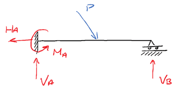
This propped-cantilever has 4 potential reactions and is therefore statically indeterminate to one degree. As a result it could withstand the formation of one plastic hinge without collapsing. If a plastic hinge were to form at support A for example as shown below, the structure would be reduced to a statically determine simply supported beam.
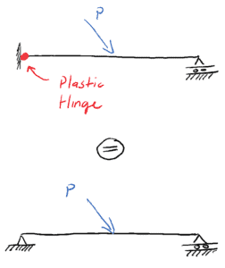
So there are really two load capacities we should be aware of for a structure. The Plastic load capacity is the load under which sufficient hinges form to cause a structure to collapse. The Elastic load capacity is the load under which any section in the structure exceeds its elastic limit.
⚠️ Only when sufficient plastic hinges have formed to exhaust all redundancy in a structure, will it collapse.
Stress-strain Curve and Plastic Deformation
So far we’ve loosely mentioned this concept of hinge formation and the resulting loss of a degree of redundancy. To better understand this, we need to take a closer look at exactly what is happening when a hinge forms in a beam.
For a plastic hinge to form, we must be dealing with an elastoplastic material. Or in other words, none of what we’re discussing in relation to plastic hinges applies to brittle materials. So, structural steel (ductile) definitely can develop plastic hinges. Glass (brittle) cannot, mass concrete (brittle without reinforcing steel) cannot but reinforced concrete can under the right circumstances because of the presence of reinforcing steel.
So, for the purposes of our discussion let’s assume we’re dealing with structural steel. Steel is an elastoplatsic material that follows Hooke’s law until the yield stress,
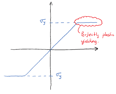
-> Plastic yielding is characterised by an increase in strain at a fixed magnitude of stress.
Structural steel is a great example of an elastoplastic material:
- It has a well defined yield point
- It undergoes large strains during yielding
- It exhibits the same material behaviour in tension and compression
Consider the stress-strain curve for structural steel (in uniaxial tension) in a bit more detail below:
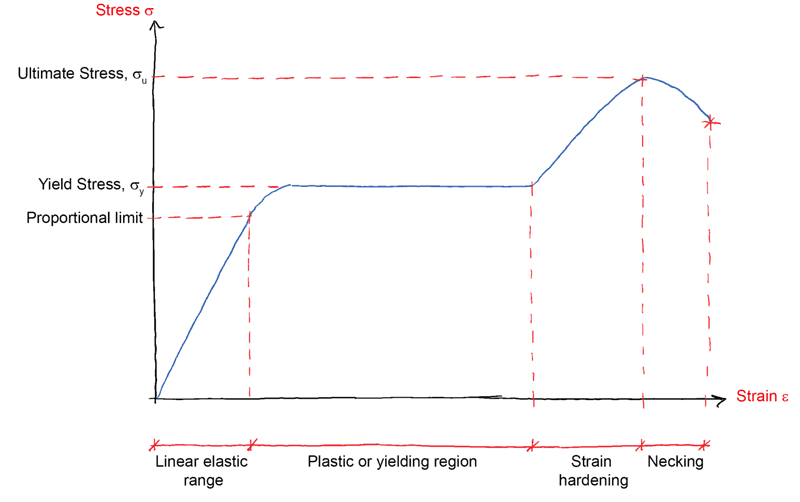
The linearly elastic range is exceeded when the tensile stress exceeds the proportional limit. This is very quickly followed by the onset of the plastic or yielding region when the tensile stress reaches the yield stress, . This plastic region is central to the formation of plastic hinges.
Of less interest but still worth noting are the regions following the plastic region. The strain hardening zone terminates at the ultimate stress, and is immediately followed by the necking region prior to rupture of the material.
The key point to take from this graph is that the plastic region is characterised by an increase in strain at a constant value of stress (the yield stress). This is the definition of plastic behaviour!
Our task now is to take this material behaviour, and map it onto beam bending behaviour. In other words, what how does this plasticity manifest in a beam undergoing bending?
Stress-strain Behaviour & Plastic Hinge Formation
Consider a beam under the influence of a progressively increasing external point load (and resulting internal bending moment) at the mid-span point. We’ll refer to the internal moment of resistance, induced by the point load as an ‘applied’ moment .
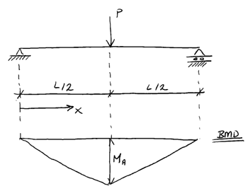
Now consider the stress in the beam cross-section at and let denote the yield stress for the beam material. From the standard bending stress equation we know the moment at which yielding of the beam material will occur,
where represents the second moment of area for the beam cross-section and represents the distance from the extreme beam fibre to the neutral axis (N.A)
💡 Remember the neutral axis is the point in the cross-section at which the longitudinal/normal stress due to bending is zero
We can now consider the different stages of behaviour the cross-section goes through as the point load is increased and we observe elastoplastic behaviour. In particular we’ll focus on the stress and strain distribution at the cross-section located at , the point of maximum moment.
Stage 1: Applied moment < Yielding moment
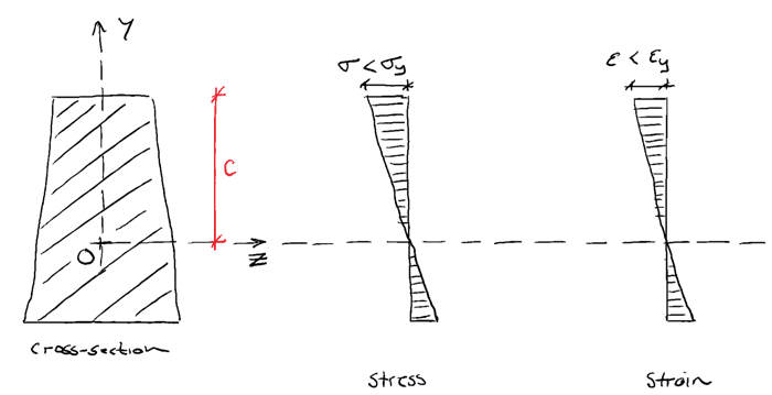
At this stage, the cross-section behaves elastically and the stress, remains below the yield stress, . This is the simplest form of cross-section behaviour to model and is what you’ve probably spent most of your time considering. As we’ll see, this linear elastic model of cross-section behaviour is somewhat inefficient as it leaves the material strength within the plastic range of behaviour untapped.
Stage 2: Applied moment = Yielding moment
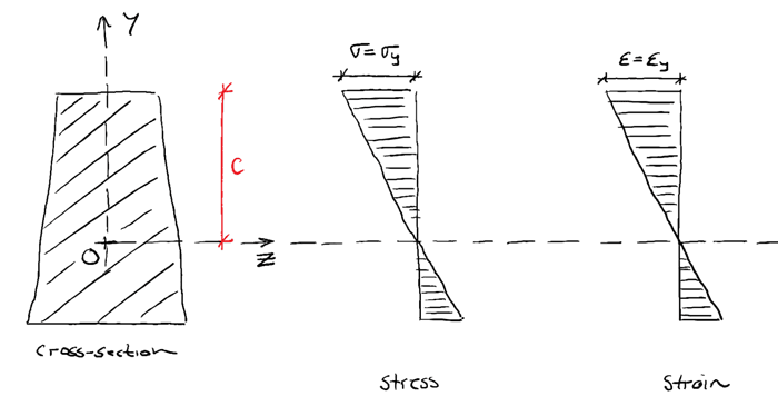
When the applied bending moment (resulting from increasing external load P remember) is increased such that the maximum normal stress due to bending , is equal to the material yield stress , the cross-section has reached the limit of the elastic range. Any further loading will cause partial yielding of the cross-section.
Stage 3: Applied moment > Yielding moment
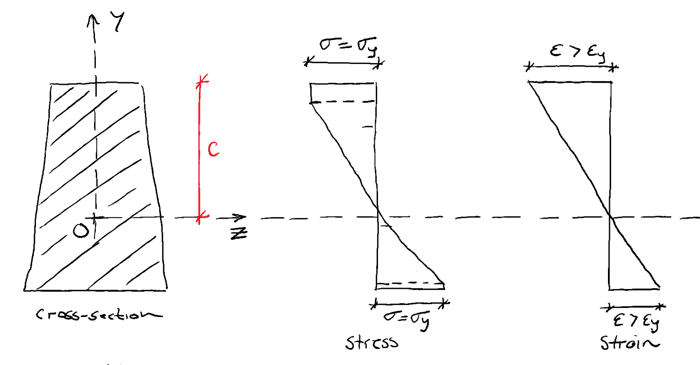
If the moment is increased further, more fibres reach the yield stress , but do not exceed it. However, strains will continue to increase beyond the yield strain. Therefore the relationship between stress and strain is no longer linear (i.e. stress is no-longer simply a constant multiple of strain). Remember, this is the definition of plastic behaviour – increasing strain for a constant value of stress.
The longitudinal stress is limited and cannot increase beyond the yield stress. So as more load is applied, more and more fibres reach this limit, which has the effect of ‘plastic regions’ developing at the outer edges of the cross-section and progressively growing towards the centre.
We end up with an elastic core, (shown in blue in the image below, with plastic regions at the outer edges of the cross-section – shown in red). At the same time the strain (and therefore rotation) at this cross-section continues to increase (green below).
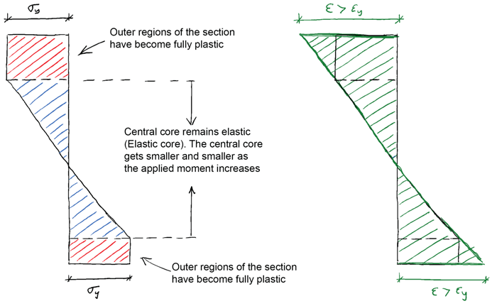
The strain must continue to increase as long as there is increasing deflection of the beam and therefore rotation at the cross-section. You might recall from basic beam bending theory that the relationship between strain at a section and curvature is,
where, is the curvature of the beam, is the radius of curvature and is the distance from the neutral axis to the point at which the strain occurs.
This relationship relates the strain behaviour at a cross-section to the deflection (specifically rotation) of the beam and explains why the strain must continuing to increase despite the fact that the stress remains constant.
Stage 4: Applied moment = Yielding moment
If the applied force is increased still further, the elastic core will continue to reduce in size until it disappears completely. At this point the section has fully yielded and can withstand no further increase in bending moment.
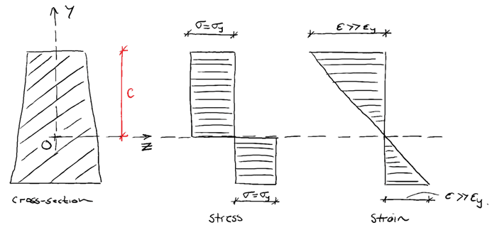
💡 The bending moment at which this point is reached (elastic core disappears) is called the Plastic Moment. This represents the full moment capacity of a cross-section.
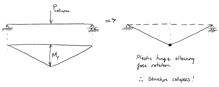
If the bending moment is increased beyond the plastic moment, the section behaves like a (plastic) hinge, allowing rotation to occur. We can see from the image below, that if the maximum moment in the statically determinate simply supported beam reaches the plastic moment, hinge formation would lead to the structure becoming a mechanism and collapsing.
We can now summarise the progression of the cross-section through various states from, from fully elastic to fully plastic,
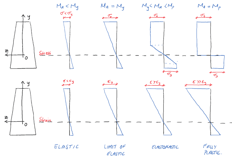
From this discussion we can see that if we have a ductile material, designating the yield moment, (the moment at which fibres in the section first reach their yield stress), as the maximum allowable moment is somewhat conservative. In reality, the cross-section has a further reserve of capacity up until full yielding of the complete section occurs.
The formation of outer plastic regions while an inner elastic core persists is known as elastoplastic bending behaviour. When we have exhausted the elastoplastic capacity of the material and the section becomes fully plastic, a plastic hinge is said to have formed. Any further loading of the structure would cause free rotation at the location of the plastic hinge.
Now that we have a good grasp conceptually of what’s going on when a hinge forms, in the next post, we’ll move on to determine the plastic moment capacity of a cross-section. We’ll also think a little more about moment redistribution in statically indeterminate structures.
Dr Seán Carroll's latest courses.



Featured Tutorials and Guides
If you found this tutorial helpful, you might enjoy some of these other tutorials.
A Pynite Crash Course - Open Source Finite Element Modelling for Structural Engineers
Part 1 - Get hands-on with V1.0 of this exciting new Python FEA library

Dan Ki


