How moment redistribution leads to more efficient designs
![[object Object]](/_next/image?url=%2Fimages%2Fauthors%2Fsean_carroll.png&w=256&q=75)
In this tutorial, we’ll discuss moment redistribution in reinforced concrete. We’ll see how we can use the plastic behaviour of reinforced concrete at the ultimate limit state to develop more efficient designs. We’ll do this by first explaining the moment redistribution behaviour in a statically indeterminate structure and then exploring what it means for the design of reinforced concrete sections.
I’ll assume that you have some familiarity with reinforced concrete section analysis. If not, read my previous article on reinforced concrete fundamentals first.
If you want to take a deeper dive into reinforced concrete design and see how we can use Python to automate some of the routine design calculations, you might find my Fundamentals of Reinforced Concrete Design to Eurocode 2 course helpful.
Fundamentals of Reinforced Concrete Design to Eurocode 2
An introduction to ultimate limit state design for bending and shear with optional calculation automation using Python.
After completing this course...
- You will be able to determine design actions using the Eurocodes Basis of Structural Design (EC0) and Actions on Structures (EC1).
- You will understand balanced section design and how to analyse and safely design singly and doubly reinforced concrete sections.
- You will understand how to apply the Variable Strut Inclination Method for shear reinforcement design.
- You will have developed your own reinforced concrete design codes in Python (the Python pathway is optional in this course).
1.0 Introduction – What is moment redistribution?
When designing any structural element, our first pass usually involves an elastic design – i.e. we assume that the materials involved all remain within their elastic range – baked into this assumption is a further underlying assumption that the materials are linearly-elastic. This is an inherently conservative approach and makes sense for our first analysis and design iteration. If the element we’re designing happens to form part of a statically determinate structure that has no structural redundancy, this is the only approach we can take since plastic hinge formation would lead to collapse!
However, if we’re dealing with a statically indeterminate structure that, by definition, has at least one degree of statical indeterminacy (redundancy), then allowing a hinge to form may be beneficial from an efficiency point of view. Assuming the materials have an acceptable degree of ductility to allow hinge rotation to occur, hinge formation allows internal bending moments within the structure to be redistributed as further load is applied after the hinge has formed – this is moment redistribution.
Put another way, moment redistribution refers to the process by which internal bending moments are redistributed within a continuous reinforced concrete member, typically beams, to improve structural efficiency. This phenomenon arises due to the ductile nature of steel reinforcement and the nonlinear stress-strain behaviour of a reinforced concrete section.
Again, it can’t be stressed enough that plastic hinge formation and the resulting redistribution of moments is only acceptable in a statically indeterminate structure where hinge formation will not lead to the formation of a mechanism and collapse.
When we first discussed reinforced concrete section analysis, we derived a limit on neutral axis depth, , based on the simultaneous failure of the reinforcing steel in tension and the concrete compression block. We referred to this as a ’balanced section’. This limit was . We went on to conclude that this limit should actually be reduced to . At the time, we somewhat cryptically said that this was to allow plastic hinge formation, such that rotation of the section could take place prior to the concrete compression block crushing. Well, let’s now dig into this statement and see exactly what we meant by this.
1.1 Indeterminacy, mechanisms and plastic collapse
Let’s start with a simple example of a two-span continuous beam where the spans, , are equal and each is subject to a point load, at the mid-span location. We recognise this as an indeterminate structure in 2D since there are more than 3 reactions and therefore simple statics alone will not be sufficient to determine the unknown reactions and subsequently the internal bending moments.

Fig 1. Indeterminate 2-span continuous beam with individual span lengths, , subject to mid-span point loads, .
This structure is statically indeterminate to one degree. This means it can accommodate the formation of one hinge and remain stable. So, for example, if a hinge were to form at C, the structure would be reduced to two simply supported beams, Fig. 2.
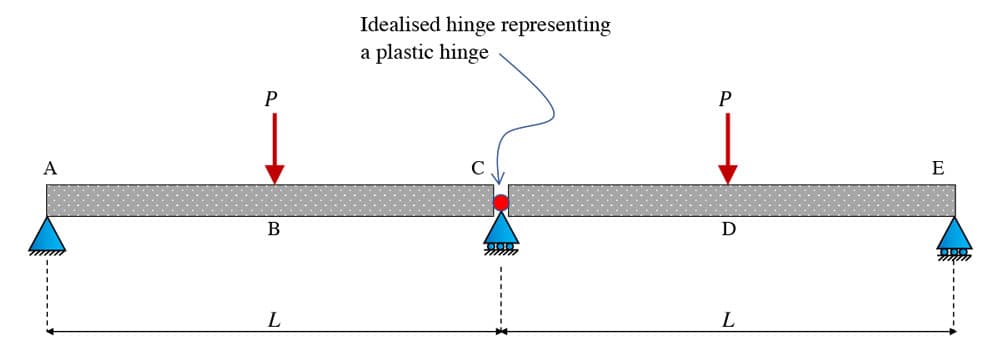
Fig 2. Hinge formation at C reduces the continuous beam to two simply supported beams.
Alternatively, if a hinge formed at either B or D, under the point loads, let’s assume a hinge at D for example, then the overall structure would remain stable since the substructure between A and D and in particular, the cantilever from C to D, would hold up the sub-structure between D and E, Fig. 3.

Fig 3. Hinge formation at D, reducing to a propped cantilever.
However, if two hinges formed, we would have either partial or total collapse, Fig. 4. So we’ve clearly established that n degree of indeterminacy only allows for the safe formation of n hinges!

Fig 4. Partial collapse due to hinge formation at C and D.
1.2 Plastic Collapse and Moment Redistribution
Now, let’s take a closer look at the bending moments that develop in this structure – starting with the elastic moments, Fig 5. Note that you could determine these moments by hand using a number of different techniques, e.g. the moment distribution method, discussed here, or the stiffness method, discussed here. For a simple structure like this, a quick moment distribution analysis is probably the way to go. Since that’s not our focus here, I’ll leave it as an exercise for you to confirm.
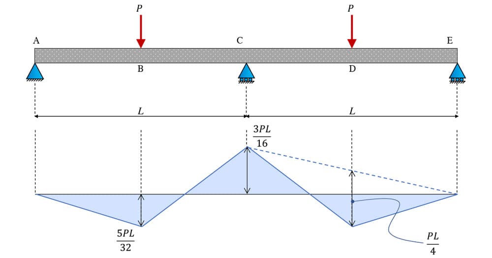
Fig 5. Elastic bending moment diagram.
Note that we’ve specifically identified the moment at the mid-span. Regardless of any variation or distribution between the hogging (at C) and sagging (at B or D) moments, this will always remain the same. This will be significant later.
With this elastic bending moment diagram as our baseline, we can now embark on a thought experiment to tease out this idea of moment distribution. Suppose this is actually a reinforced concrete beam, and we continue increasing the magnitude of . Since the hogging moment at C is larger than the sagging moments at B and D, yielding will occur here first.
Recall the typical moment-curvature behaviour of a reinforced concrete section, Fig. 6. Deformation of the structure and, therefore, rotation at C will continue as the load is increased until some yielding moment, , is reached. Provided the cross-section is ductile enough, the internal reinforcing steel will begin to yield, and very shortly thereafter, we reach a moment, , the plastic moment for the section.
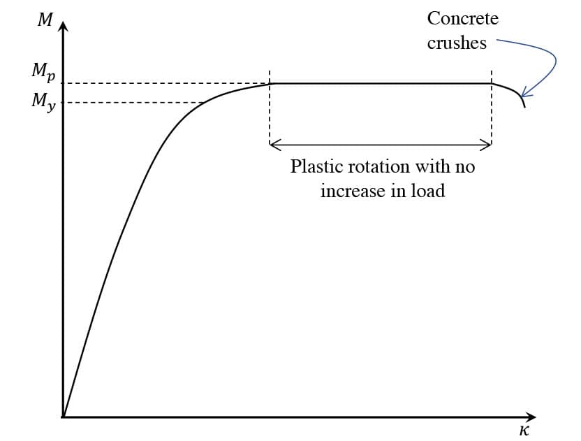
Fig 6. Idealised moment-curvature relationship for a reinforced concrete section.
If more load is applied after is reached at C, the structure will behave as if a rotational hinge exists at C. Additional loading will cause free rotation at C, since the section at this location can resist no further increase in loading. This is indicated by the horizontal line in the moment-curvature graph above. One big assumption here is that rotation can continue to occur at C without the concrete compression block crushing – more on this later.
At this stage in our experiment, the moment at C is fixed – it cannot increase any further. So, what happens if we continue increasing the magnitude of the point loads? The spans behave effectively as two simply supported beams in response to additional loading. This means that the sagging moments will continue increasing.
However, equilibrium must be maintained – this is where the moment we identified earlier comes back into the picture. If the moments at B and D are increasing, then the moment at C must be reduced if, the constant moment at the mid-span, , is to be maintained, Fig 7. This is where the term moment redistribution comes from – the formation of a hinge at C has the effect of redistributing the moment into the adjacent spans. Some engineers will loosely refer to load being ’shed’ into the spans.
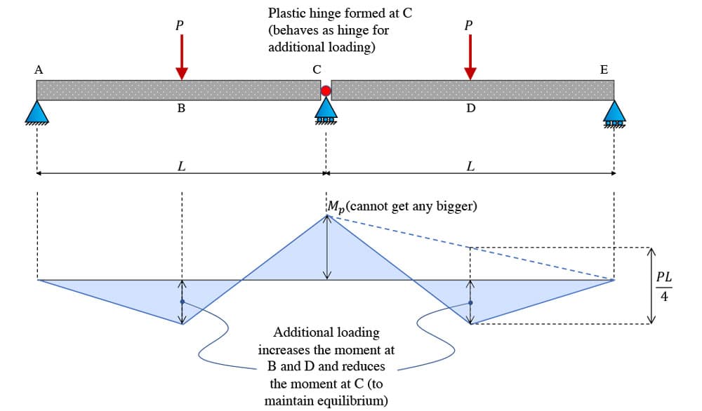
Fig 7. Moment redistribution from C at the support (hogging) to B and D (sagging) in the adjacent spans.
The moment at the mid-span locations is,
Now, if we keep increasing the magnitude of , at some point the beam sections at B and D will also yield and hinges will form. This represents the collapse condition for the structure – when the bending moment at B, C and D equals , Fig 8.
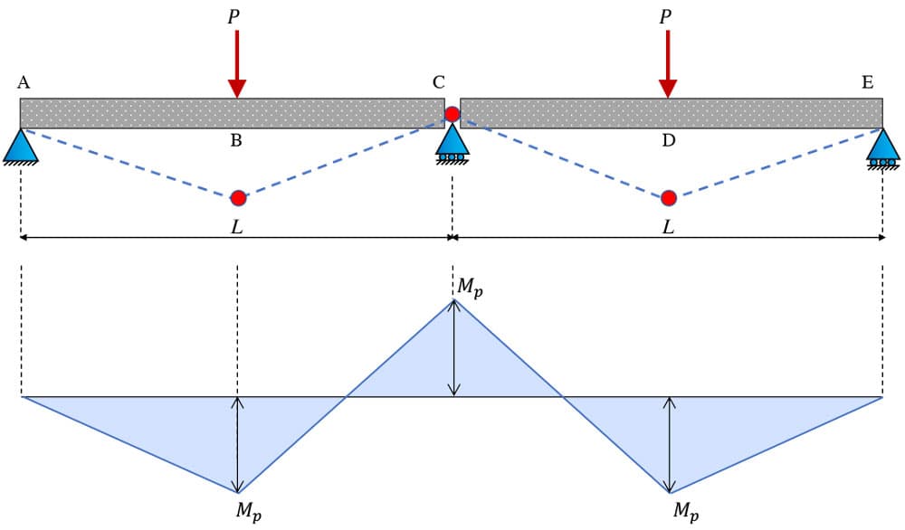
Fig 8. Plastic collapse due to hinge formation at B, C and D with moment .
If we note that , equation (1) can be written as,
So, the plastic bending moment diagram, at collapse, is quite different to the initial elastic bending moment diagram. It’s helpful to compare the two, side by side, Fig 9.
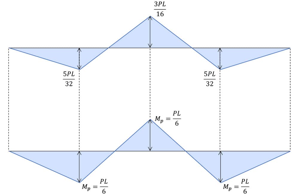
Fig 9. Elastic bending moment diagram (top), and plastic bending moment diagram at collapse (bottom).
We note the magnitude disparity between the hogging and sagging moments in the elastic bending moment diagram. After the formation of the first plastic hinge at C, moment redistribution takes place, and the moment begins to be redistributed into the spans until they also reach their elastic limit. The hinge has allowed the elastic moment at C to be reduced, and in return, the moments at B and D have been increased from their elastic values – again, this is moment redistribution. Note also that in each case, equilibrium is maintained; for the mid-span moment in the elastic case, we have,
and for the plastic case,
Remember, this whole redistribution process assumes that the section at C is ductile enough to allow sufficient rotation to take place after the tension steel has yielded but before the concrete compression block crushes, Fig 10. The window of loading between these two events is what we facilitate by limiting the neutral axis depth to . As rotation occurs, post hinge formation, the neutral axis for the section will move towards the balanced failure limit of . When this limit is reached, the concrete compression block will crush, the hinge will be destroyed, and the integrity of the structure will be fatally compromised.
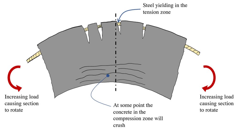
Fig 10. Hinge rotation at C.
At this point, our experiment has concluded and we’ve explored the full range of behaviour for our beam – going beyond the elastic range, right up to plastic collapse. Clearly, if we only design a structure for the maximum elastic moment, we’re leaving some capacity on the table. In an effort to be as efficient as possible in our design, we should take advantage of this extra capacity in the structure. It’s also clear that this approach is only valid when we have clear redundancy in our structure.
Now we can start to explore how to adapt our reinforced concrete design so that we can take advantage of moment redistribution in a structure.
2.0 Moment redistribution and reinforced concrete design
We’ve already mentioned above the purpose of limiting the neutral axis depth at the ultimate limit state is so that the section will have sufficient rotational capacity after the steel yields. We’ve seen the limit, a number of times now. However, this is just one possible value of the limit on neutral axis depth. More specifically, it’s the limit that is applied when no moment redistribution has been assumed in design.
If our design seeks to take advantage of moment redistribution, we must further reduce this limit to ensure sufficient rotational capacity exists. To get our bearings, let’s revisit the typical strain diagram for a reinforced concrete section, Fig 11.
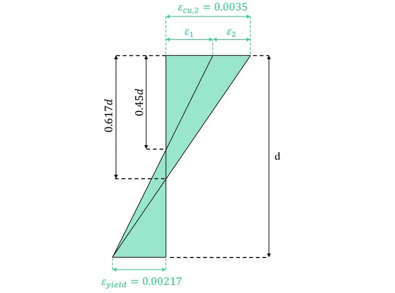
Fig 11. Limits on neutral axis depth, previously defined and discussed here
We last saw this diagram in the previous tutorial when we discussed fundamental section analysis. Note that the strain on the bottom is the steel yield strain. When we limit the neutral axis depth to , the strain on the top surface – the maximum compression strain in the concrete, is – some value less than the rupture strain for concrete, .
In order for the strain in the concrete to reach the rupture strain, the neutral axis must migrate down to . At this depth, the section is said to be balanced since the concrete and steel are simultaneously failing. So, the neutral axis depth range between and represents the window in which plastic hinge rotation of the section can occur, after the steel yields but before the concrete crushes.
Now, if we want to take advantage of moment redistribution and explicitly allow for hinge rotation such that the moment will actually be able to distribute according to our structural analysis, we may need to peg the neutral axis back even further than . This essentially ensures that our section is ductile enough to accommodate the degree of hinge rotation we’re relying on achieving.
2.1 Designing for moment redistribution
We start by defining the ratio between the moment at a section after distribution to the moment before distribution, ,
To ensure the section remains ductile enough,
where the factors and are prescribed by the Eurocode 2. The UK NA to EC2 specifies and , so the limiting value of neutral axis depth, as a function of moment distribution, is,
where is the effective depth of the section. Note that more generally, when the UK national annex is not applied, EC2 specifies and .
For our two-span beam above, considering the hogging moment at C,
So, the limits on neutral axis depth would be , defaulting to using factors from the UK NA and using the general EC2 factors. The more moment redistribution we require, the more plastic hinge rotation that must be facilitated and the smaller (or higher up, assuming tension on the bottom face) the limit on neutral axis depth must be. Once an appropriate value for the limiting neutral axis depth is established, the rest of the section design proceeds as discussed in the previous post. For completeness, we’ll consider an example here.
2.2 Example section analysis with moment redistribution
Consider a reinforced concrete cross-section with the following parameters:
- width,
- height,
- effective depth,
- Concrete characteristic cylinder strength,
- Steel characteristic yield strength,
The beam is subject to a design hogging moment, . This moment has been determined by allowing for a redistribution of moments, in other words, the moment has been reduced by .
Our task is to determine an arrangement of steel reinforcement that will allow sufficient rotation at the section such that a reduction can be realised.
We will assume the general definition of and , rather than the values defined in the UK national annex, therefore, and . The solution proceeds as follows.
(i) Determine the max allowable neutral axis depth
A reduction means that the distribution ratio is, . Therefore the is given by,
(ii) Calculate the lever arm, , and moment of resistance,
The lever arm is given by,
The moment of resistance is now calculated as the product of the compression force in the concrete, , and the lever arm we just calculated.
Since the calculated moment of resistance is less than the design moment, we will make use of compression zone reinforcement to increase the moment capacity.
(iii) Compression reinforcement
The calculation of the required area of compression reinforcement, , assumes that the compression steel has yielded at the ultimate limit state. For this to be true, we must ensure the compression steel is placed close enough to the compression surface, in this case (hotting moment), this is on the bottom of the beam. We must ensure that the effective depth to the compression steel, , satisfies,
On this basis, let’s let .
Now the area of compression steel, , can be calculated as,
This area of compression reinforcement can be sensibly achieved by providing H20 bars .
(iv) Tension steel
Finally, we can calculate the required area of tension reinforcement, ,
This area of reinforcement can be provided by H32 bars (2410:mm^2). Note that we are designing for a hogging moment, the H32 bars will be positioned at the top of the beam and the H20 bars will be positioned on the compression zone at the bottom of the beam.
This concludes the bending analysis for the section under consideration.
3.0 Wrapping up
Now you should have a good first principles understanding of moment redistribution and how it ties directly into the design of reinforced concrete cross-sections. This is an important concept to understand, particularly as you start to explore beyond the fundamentals of reinforced concrete design.
By taking advantage of the plastic hinge formation and the resulting moment redistribution, engineers can deliver more efficient designs, ultimately reducing the cost and carbon footprint of reinforced concrete structures.
If you want to learn more about reinforced concrete design and how to apply Eurocode 2, take a look at my recent course, ’Fundamentals of Reinforced Concrete Design to Eurocode 2 ’. In it we develop the design equations for bending and shear from first principles and, once comfortable with the theory, we use Python to automate many of the common time-consuming analysis procedures.
That’s all for this one – I’ll see you in the next one!
Dr Seán Carroll's latest courses.



Featured Tutorials and Guides
If you found this tutorial helpful, you might enjoy some of these other tutorials.
Column Buckling and Stability
Long slender structural elements in compression will typically fail due to buckling rather than direct compression. In this post we'll explore column buckling

Dr Seán Carroll

