Plastic Analysis of Frames – A Complete Guide – Part 2
![[object Object]](/_next/image?url=%2Fimages%2Fauthors%2Fcallum_wilson.jpg&w=256&q=75)
Welcome to the second of this two-part tutorial series focussed on plastic analysis methods. This part builds on what we discussed in part one, so make sure to read that first if you haven’t done so already.
By the end of this tutorial, you will be confident in applying plastic analysis methods to single and double bay frame structures (which are extremely common in the practical world of structural engineering!).
All Access Membership
Learn, revise or refresh your knowledge and master engineering analysis and design
Access Every Course and Tool
- Over 1040 lectures & over 212 hours of HD video content
- Access member-only 'deep dive' tutorials
- Access all downloads, pdf guides & Python codes
- Access to the StructureWorks Blender addon + updates
- Packed development roadmap of courses & tutorials
- Price Guarantee – avoid future price rises as we grow
- Priority Q&A support
- Course completion certificates
- Early access to new courses
1.0 A short recap from part one
In part one, we developed an understanding of the importance of plastic analysis methods, defined a check-list to ensure that plastic analysis is suitable for a given structure and we applied two separate methods of plastic analysis to indeterminate beams; the equilibrium method and the mechanism method.
Within part one we also discussed the importance of the uniqueness theorem. The uniqueness theorem tells us that there is a unique collapse load factor for each structural system.
The uniqueness theorem contains three criterion which must be satisfied before we can confirm that we have identified the unique (and lowest) collapse load factor. If you can’t recall these three criterion, take a moment to check back in with part one!
Lastly, we showed that the two different methods of plastic analysis (equilibrium and mechanism) resulted in equal values when the unique collapse load was identified. This tells us that we can use either method to obtain the critical collapse load (i.e. the lowest).
So let us start thinking about plastic analysis in the context of frames.
2.0 What is a frame? Are all frames the same? Can we apply plastic methods to all frames?
Previously, we discussed a five point check-list which we had to complete before continuing to use plastic analysis techniques. The fourth point in this checklist asked Are we happy that all structural connections are able to transmit the plastic moment ?. When studying beam-type systems, we are not concerned about structural connections because we are assuming a single member…but this is not the case when considering frame systems.
Ok, so this should lead us to think that structural frames are systems which manifest as a set of beam type elements connected together. It might help you to think of the the vertical elements within frames as columns and the horizontal elements as beams.
We can make a simple distinction between the two most common types of frame system by considering the behaviour of the connections between individual elements within a frame.
We commonly refer to the location of these connections as joints. If the joints within a frame system provide resistance to bending moments then we refer to this frame type as a moment resisting frame. However, if the joints within a frame system are designed as pinned, then there is no moment resistance at the joints and we refer to this frame type as a braced frame.
Both moment resisting and braced frames are extremely popular structural forms, and in reality their general appearance is very similar. However, their structural behaviour is vastly different!
So let us answer our final question….‘can we apply plastic analysis methods to all frames’?. The answer to this should now be clear…but let’s think about it logically.
In part one, we discussed the concept that as additional load is applied to a structure, bending moments are redistributed around the structure due to the formation of plastic hinges. So, if we want to redistribute bending moments from one frame member to another, then as a minimum, the joint between these two members must be able to transmit the plastic moment . Immediately, therefore, we can say that plastic analysis is not suitable for braced frame structures because the joints cannot resist any bending moment, let alone the plastic moment .
So the key point to take away is that we can only apply plastic analysis methods to moment resisting frames.
3.0 Equilibrium Method vs Mechanism Method
Both of the plastic analysis methods developed previously are applicable to the analysis of moment resisting frames. However, when applied to frames, there can be no doubt that the mechanism method is much simpler to implement than the equilibrium method. Why is this?
The equilibrium method is most useful when we know the collapse mechanism. For simple beam type problems we could reasonably suggest a few possible collapse mechanisms and check the equilibrium, mechanism and yield conditions (of the uniqueness theorem), so this made the equilibrium method well suited to beam-type problems.
However, in the analysis of plastic frames, and without prior knowledge of typical frame collapse mechanisms, creating a collapse mechanism, checking the resulting bending moment diagram against the uniqueness criterion and then repeating for an infinite number of ‘potential’ collapse mechanisms is extremely arduous.
What is more sensible is to apply the mechanism method. In the analysis of plastic frames this method is often referred to as the ‘method of combining mechanisms’. This alternative name gives us a clue about how we are going to implement the mechanism method on plastic frames.
In fact, this ‘method of combining mechanisms’ tells us that for a given plastic frame, each unique collapse mechanism can be thought of as a combination of multiple well defined, and common, independent mechanisms. So let us make a start with out first example.
Example 1: Symmetric Single-Bay Plastic Frame
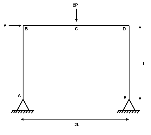
Fig 1. Example 1 general arrangement
Step 1: Identify the degree of determinacy of the structure
We have four reactions (, , and ) and three equilibrium equations (, and ).
Therefore, the degree of indeterminacy is .
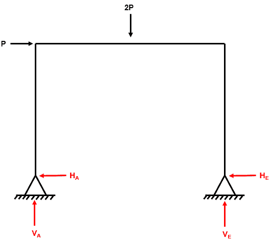
Fig 2. Example 1 degree of indeterminacy
Step 2: Determine all locations where plastic hinges could form
As discussed in part one, a simple rule of thumb to follow is that plastic hinges CAN form at the following locations in a beam:
- At points where concentrated loads are applied
- At points of zero shear force (i.e. points of inflection in a bending moment diagram)
- At supports which can develop a moment i.e. fixed or continuous
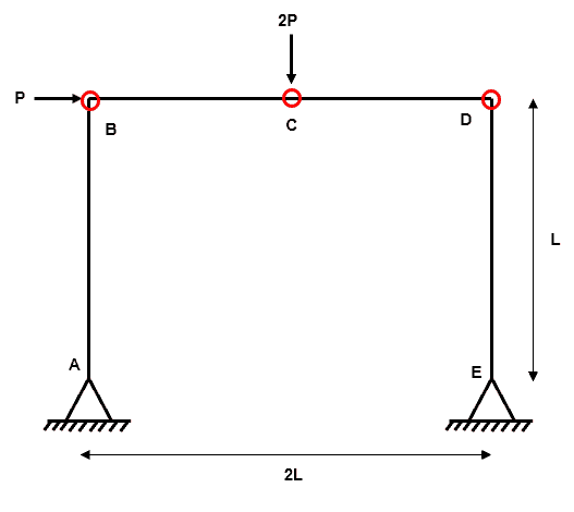
Fig 3. Example 1 locations of possible plastic hinges
For example 1, we have three possible plastic hinge locations ().
Step 3: Define and determine all independent collapse mechanisms
An independent mechanism is an arrangement of plastic hinges within the system which will result in plastic collape. We have a system which has plastic hinge locations and is indeterminate to the 1st degree ().
A simple rule to follow when determining the total number of independent collapse mechanisms is that:
where is the total number of possible independent mechanisms.
Independent Mechanism 1
The first independent mechanism is referred to as a ‘beam-type’ mechanism. Why?….well it is identical to the beam collapse mechanism which we identified in part one. This is the simplest type of frame collapse mechanism.
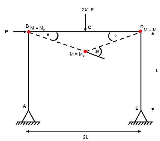
Fig 4. Example 1 independent mechanism 1
Independent Mechanism 2
The second independent mechanism is referred to as a ‘sway-type’ mechanism. The sway type mechanism is rather intuitive as it is most likely the collapse mechanism we think of first when considering laterally loaded plastic frames.
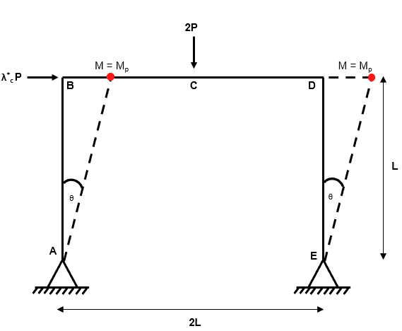
Fig 5. Example 1 independent mechanism 2
Step 4: Define and determine all composite collapse mechanisms
Composite (or combined) mechanisms manifest by combining two independent mechanisms.
We have a rule of thumb for determining how many combined mechanisms we should be looking for:
where is the total number of independent and composite mechanisms.
And since we know the number of independent mechanisms, we can define as the number of composite mechanisms.
Therefore, we are looking for a single composite mechanism.
Composite Mechanism 1
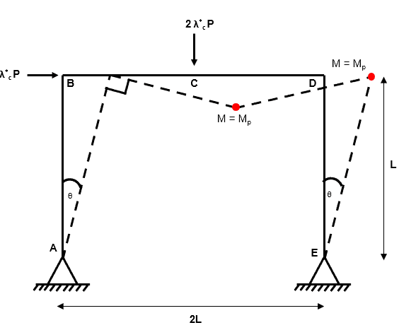
Fig 6. Example 1 composite mechanism 1
This is our composite collapse mechanism. We arrive at this composite collapse mechanism by adding together independent mechanism 1 and independent mechanism 2.
You will have noticed that by combining two independent collapse mechanisms, we have removed a plastic hinge (from independent mechanism 1). This process is known as hinge cancellation. But how does hinge cancellation work? We have to consider the magnitude and direction of rotations…
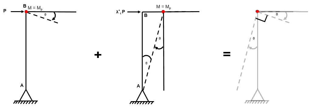
Fig 7. Example 1 hinge cancellation
Examining the joint at B we can see that the rotations at B from independent mechanism 1 and 2 have equal magnitude and direction. As a consequence, when we combine the two independent mechanisms, the angle between member BD and member BA is 90.
If the final angle between these members is 90 and the undeformed angle between these members is 90, then no net rotation has occurred at this joint and therefore a plastic hinge cannot have formed.
Step 5: For each collapse mechanism from (3) and (4), calculate using the virtual work method
and from this simple statement we can say:
Independent Mechanism 1
Independent Mechanism 2
Composite Mechanism 1
Step 6: Select the mechanism that gives the lowest and check that
We have identified that the composite mechanism is the critical case because it results in the lowest value for . As discussed in part one of this tutorial, use of the mechanism method of plastic analysis guarantees that we are satisfying the equilibrium and mechanism criteria of the uniqueness theorem, so all that we have left to check is the yield criteria.
To do this, we need to check that there are no points in the structure where . This can quickly be achieved by drawing a bending moment diagram for the entire structure.
To do this, we can split our frame into a set of single beam elements. We know that the system is indeterminate to the first degree so we only need to find one of the redundant reactions in order to draw the bending moment diagram for the entire structure. Let us isolate member DE.
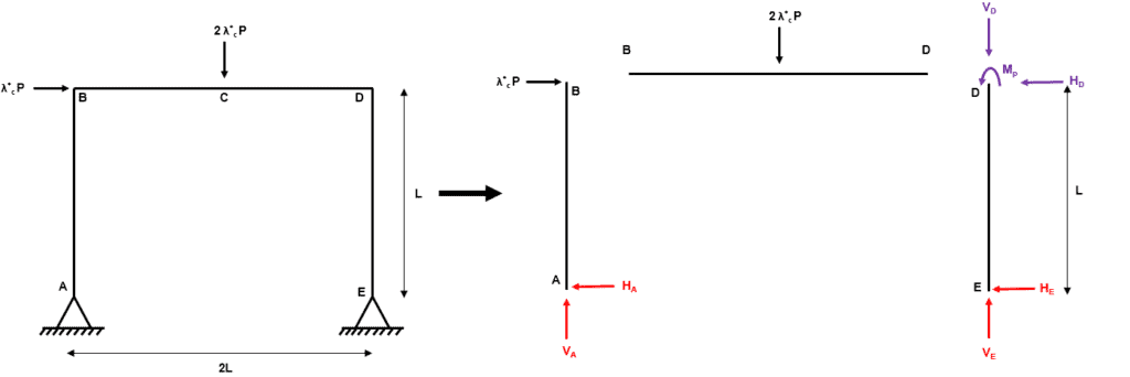
Fig 8. Example 1 global equilibrium
Now we consider equilibrium within the isolated member DE:
At this point our overall frame structure becomes statically determinate and so we can invoke our three global equilibrium conditions (, and ) to solve for the unknown reactions.
Great, we have solved for all of the unknown reactions, now we can draw the bending moment diagram for the entire frame to check the yield criterion.
And here it is…..(note that the bending moment is drawn on the tension side of the frame members).
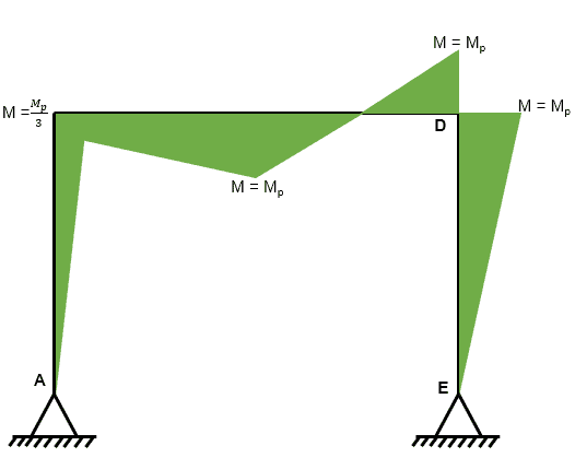
Fig 9. Example 1 bending moment diagram
We can clearly see that the bending moment does not exceed in any location which tells us that the yield criterion is satisfied.
Therefore, we have successfully found the collapse load factor which satisfies the uniqueness theorem and so .
Let us move onto example 2.
4.0 At the joint or in the member?
At this point we need to take a moment to develop our understanding of hinge locations, this will be very important for examples 2 and 3.
In example one, we assigned the position of potential plastic hinges using the set of guidelines defined in part one. Furthermore, we also stated that a pre-requisite of a frame to allow plastic analysis to be conducted is that connections between members must be able to transmit the plastic moment .
It is clear, therefore, that if we have two members with different , that the connection MUST have, as a minimum, the ability to transmit the larger of the two . So in such a connection, what is the weakest point? Well it makes sense that plastic hinges will form at the weakest point (corresponding to the lowest ).
So, in the next examples, we need to be careful to identify exactly where the plastic hinge will form. Will it form exactly at the connection? Or will it form away from the connection? The answer to this is driven by the variation in around the connection.
Example 2: Asymmetric Single-Bay Plastic Frame
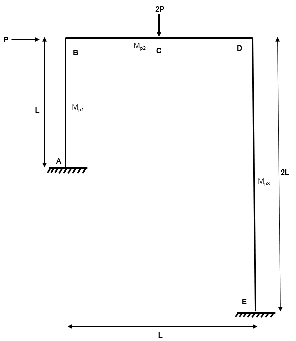
Fig 10. Example 2 general arrangement
So our second example is more complicated on two counts. Firstly, the geometry of the frame is asymmetric. Whilst more uncommon, this geometry can occur in practise if a plastic frame is supported off an existing structure at one end, for example.
Secondly, the beams and columns which make up the frame have different plastic moment capacities. This is certainly realistic as columns have lower bending capacity than beams (check out the difference between UKB and UKC sections if you are not convinced!).
But do not be put off by this added complexity, We’ll follow our normal steps to perform the plastic analysis.
Before we start, let’s set values for a number of the variables in this problem. In practise, we would normally have the length of the members and we could make an estimate of the plastic moment capacity of each member. For this example, let’s consider
Step 1: Identify the degree of determinacy of the structure
We have six reactions (, , , , and ) and three equilibrium equations (, and ).
Therefore, the degree of indeterminacy is .
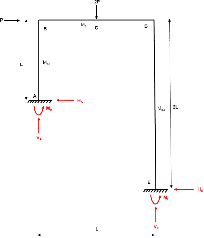
Fig 11. Example 2 degree of indeterminacy
Step 2: Determine all locations where plastic hinges could form
As already discussed, we know that plastic hinges CAN form at the following locations in a beam:
- At points where concentrated loads are applied
- At points of zero shear force (i.e. points of inflection in a bending moment diagram)
- At supports which can develop a moment i.e. fixed or continuous
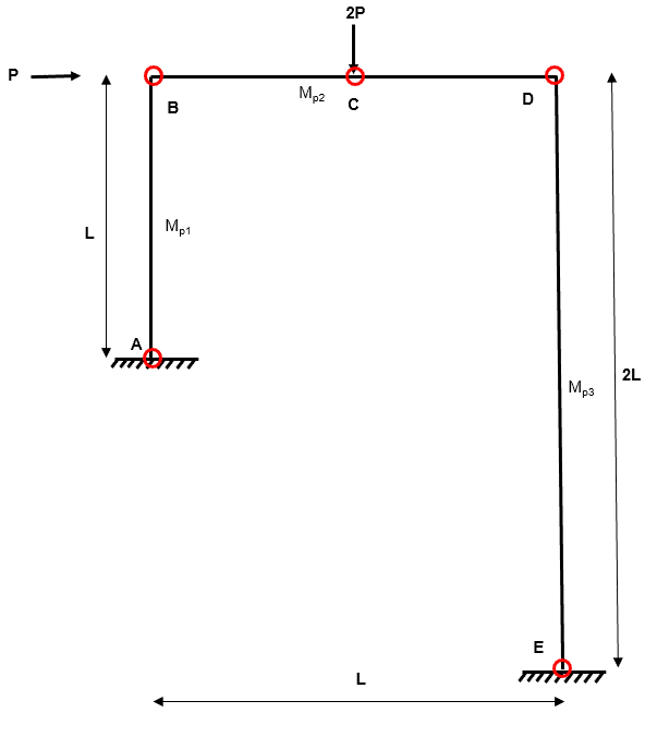
Fig 12. Example 2 location of possible plastic hinges
For example 2, we have five possible plastic hinge locations ().
Step 3: Define and determine all independent collapse mechanisms
We know that an independent mechanism is an arrangement of plastic hinges within the system which will result in plastic collape. We have a system which has plastic hinge locations and is indeterminate to the 1st degree ().
We can calculate the number of independent collapse mechanisms as:
where is the total number of possible independent mechanisms.
Independent Mechanism 1
The first independent mechanism is again a ‘beam-type’ mechanism. It is is sensible to consider this simple type of collapse mechanism within any plastic collapse analysis.
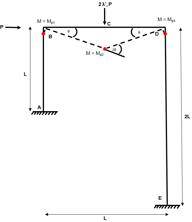
Fig 13. Example 2 independent mechanism 1
Independent Mechanism 2
The second independent mechanism is referred to as a ‘sway-type’ mechanism.
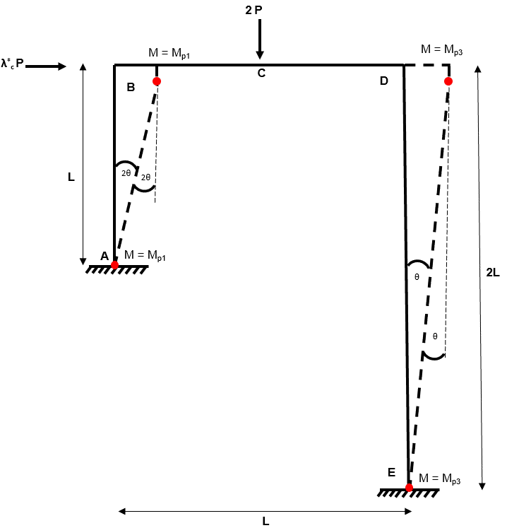
Fig 14. Example 2 independent mechanism 2
Step 4: Define and determine all composite collapse mechanisms
Composite (or combined) mechanisms manifest by combining two independent mechanisms. The number if combined mechanisms is calculated as:
where is the total number of independent and composite mechanisms.
And since we know the number of independent mechanisms from (3), we can define as the number of composite mechanisms.
Therefore, we are looking for a single composite mechanism.
Composite Mechanism 1
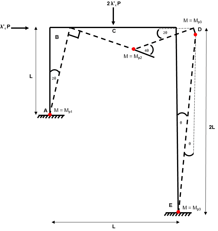
Fig 15. Example 2 composite mechanism 1
This is our composite collapse mechanism. We arrive at this composite collapse mechanism by adding together independent mechanism 1 and independent mechanism 2.
Again we note that hinge cancellation has removed one plastic hinge.
Step 5: For each collapse mechanism from (3) and (4), calculate using the virtual work method
and from this simple statement we can say:
Independent Mechanism 1
Independent Mechanism 2
Composite Mechanism 1
Note: Remember that is a multiplier which tells us how much larger the nominal applied load P needs to be in order for the plastic collapse mechanism to become a reality.
Step 6: Select the mechanism that gives the lowest and check that
Ok, so independent mechanism two results in the smallest value for and hence is critical. As per example 1, we now have to confirm that this collapse mechanism satisfies the yield criterion. Let us start by determining the unknown reactions.
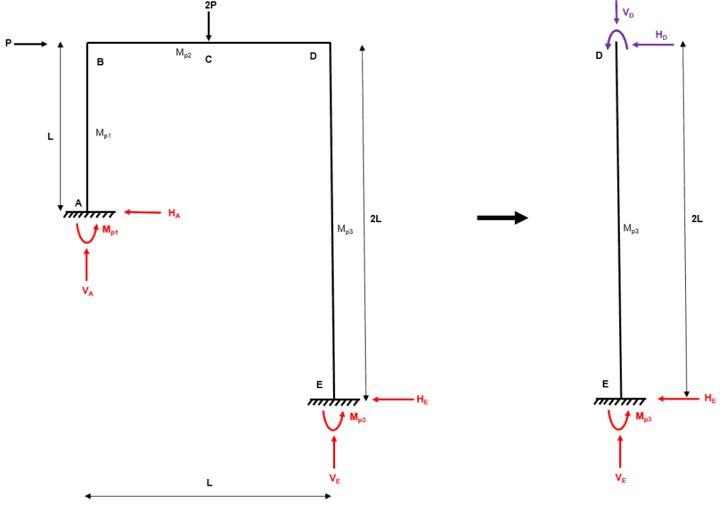
Fig 16. Example 2 global equilibrium
Now we consider equilibrium within the isolated member DE:
At this point our overall frame structure becomes statically determinate and so we can invoke our three global equilibrium conditions (, and ) to solve for the unknown reactions.
Great, we have solved for all of the unknown reactions, now we can draw the bending moment diagram for the entire frame to check the yield criterion.
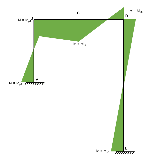
Fig 17. Example 2 bending moment diagram
We can clearly see that the bending moment does not exceed in any location which tells us that the yield criterion is satisfied.
Therefore, we have successfully found the collapse load factor which satisfies the uniqueness theorem and so .
Let us move onto example 3.
5.0 Understanding hinge cancellation
So far, we have encountered two types of independent mechanism; beam mechanisms and sway mechanisms. These are easy enough to understand and are common to all plastic frame problems. We have happily combined these two mechanisms to form composite mechanisms and we have been conscious of hinge cancellation when coincident hinges from the different independent mechanisms are combined.
We need to develop our approach to hinge cancellation for the final example
Let us remind ourselves what we have said about the virtual work method…
and from this simple statement we can say:
Hence, the smaller we can make , the smaller the collapse load factor will be. After all, we are searching for the smallest collapse load factor which satisfies the uniqueness theorem.
It should be clear by now that hinge cancellation has the effect of reducing . In the previous two examples we have only had one composite mechanism to consider and the location of a hinge cancellation was clear.
So, in the next problem (which is significantly more developed than the previous two), we need to be aware of all the possible locations where hinge cancellation can occur. This is extremely important because as discussed above, hinge cancellations reduce , which reduces .
This notion leads us to introduce the joint mechanism. This is the third and final type of independent mechanism encountered in plastic frames.
6.0 Joint mechanism
The joint mechanism can be thought of as a ‘dummy‘ independent mechanism. Yes it is true that on its own it does correspond to an independent collapse mechanism, but this collapse would only be instigated by an externally applied bending moment at the joint….this is extremely unlikely in a plastic frame.
The importance of the joint mechanism is truly revealed when we consider composite mechanisms. The joint mechanism is essentially a ‘sink’ for internal work (). Why is this relevant?….well as we discussed above, by reducing we reduce .
Ok, so you might be asking yourself how do I spot when a joint mechanism is present? It is rather simple in fact…
‘a joint mechanism shall be considered at any joint when structural members intersect’…our next example is the first time we have encountered such an arrangement and hence the first time we need to consider the joint mechanism.
The joint mechanism takes the following form:
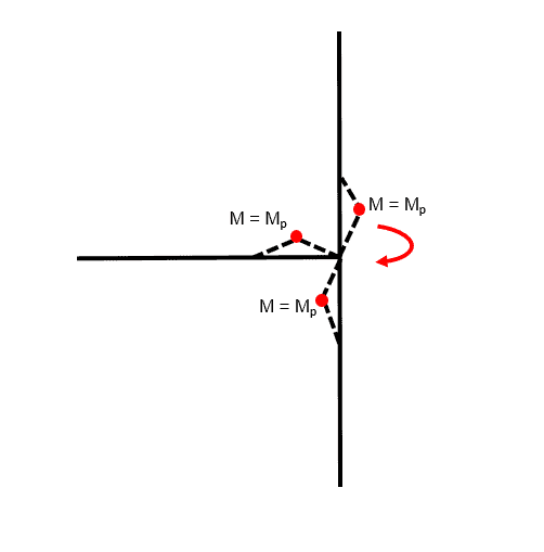
Fig 18. Example of joint mechanism
Now that we have an understanding of the joint mechanism we can proceed to tackle example 3.
Example 3: Symmetric Two-Bay Plastic Frame
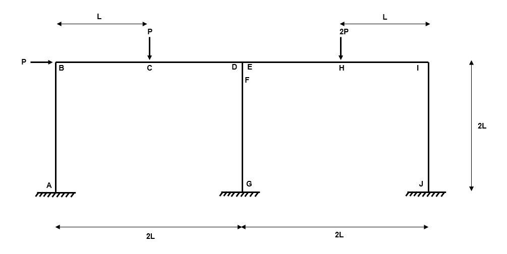
Fig 19. Example 3 general arrangement
Our third example adds a little extra complexity because we are now considering a two-bay plastic frame. I’m sure you have seen large warehouse structures which have multiple doors…these are likely to be double (if not triple) bay plastic frames.
As we will discover, the addition of this extra bay adds a significant amount of work to the plastic analysis. Therefore, for simplicity, we will consider a constant value for across all members.
To avoid lots of symbolic algebra later in the analysis, we will set the following values:
So how shall we begin?
Let’s start with step one within our plastic analysis process.
Step 1: Identify the degree of determinacy of the structure
We have nine reactions , , , , , , , and and three equilibrium equations , and .
Therefore, the degree of indeterminacy is .
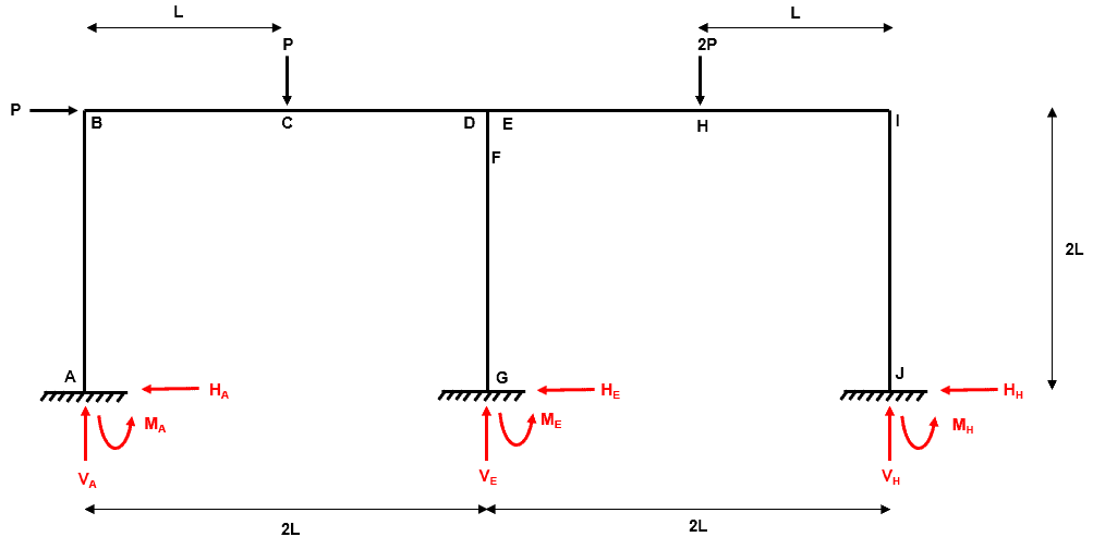
Fig 20. Example 3 degree of indeterminacy
Step 2: Determine all locations where plastic hinges could form
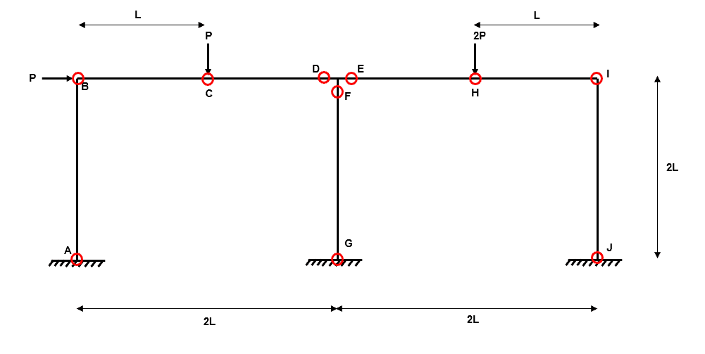
Fig 21. Example 3 location of plastic hinges
For example 3, we have ten possible plastic hinge locations . Make sure to refer back to the section on the joint mechanism if you don’t follow the reason for the three central hinges at , , and .
Step 3: Define and determine all independent collapse mechanisms
We have a system which has plastic hinge locations and is indeterminate to the 6th degree (). The total number of independent collapse mechanisms is:
where is the total number of possible independent mechanisms.
Note: recall that all members have equal
Independent Mechanism 1
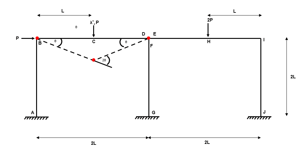
Fig 22. Example 3 independent mechanism 1
Independent Mechanism 2
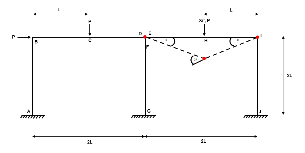
Fig 23. Example 3 independent mechanism 2
Independent Mechanism 3
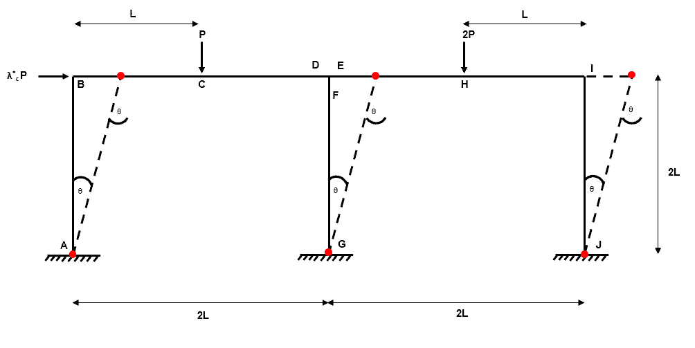
Fig 24. Example 3 independent mechanism 3
Independent Mechanism 4
Independent mechanism 4 is the joint mechanism we discussed prior to starting this example. We can consider the orientation of rotation in either direction and we will arrive at the same set of composite mechanisms.
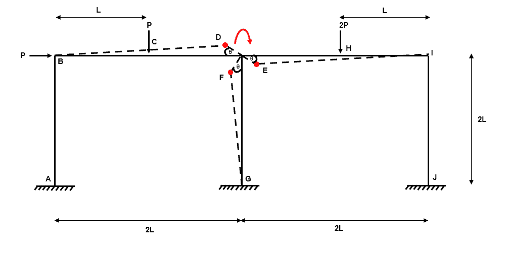
Fig 25. Example 3 independent mechanism 4a
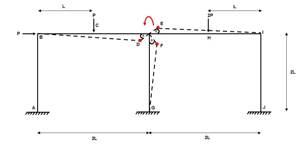
Fig 26. Example 3 independent mechanism 4b
Step 4: Define and determine all composite collapse mechanisms
The number of combined mechanisms we should be looking for is calculated as:
where is the total number of independent and composite mechanisms.
Therefore is:
So, we are looking for 11 composite mechanisms….that’s right…11!
Composite Mechanism 1
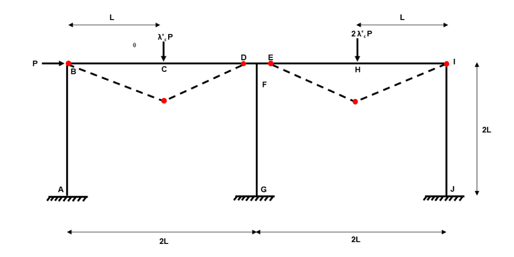
Fig 27. Example 3 composite mechanism 1
Composite Mechanism 2
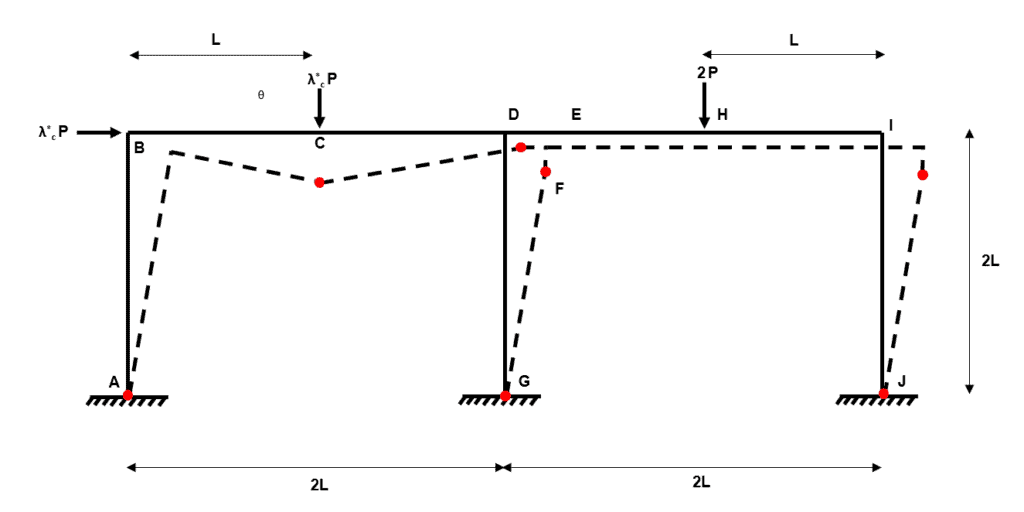
Fig 28. Example 3 composite mechanism 2
Composite Mechanism 3
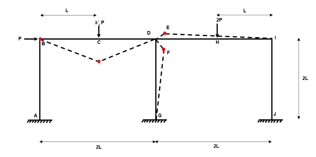
Fig 29. Example 3 composite mechanism 3
Composite Mechanism 4
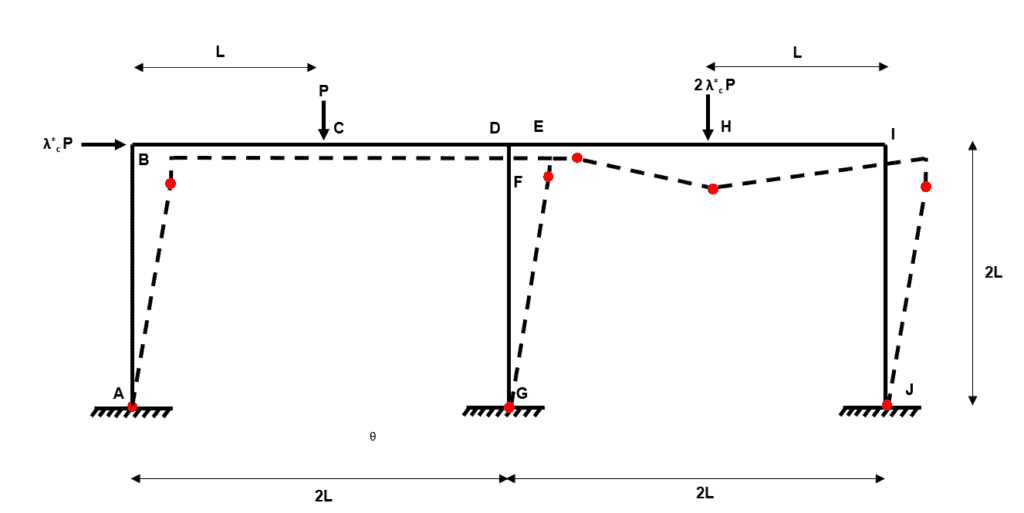
Fig 30. Example 3 composite mechanism 4
Composite Mechanism 5
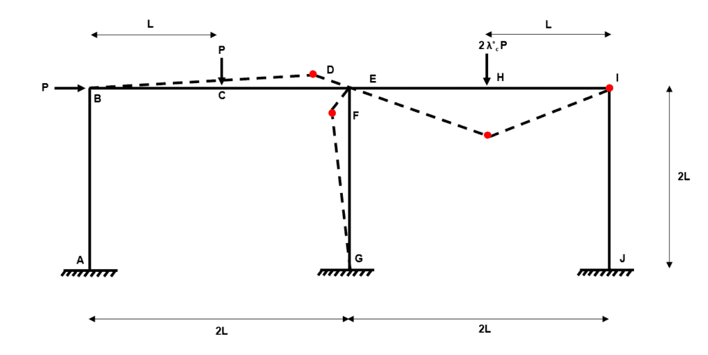
Fig 31. Example 3 composite mechanism 5
Composite Mechanism 6
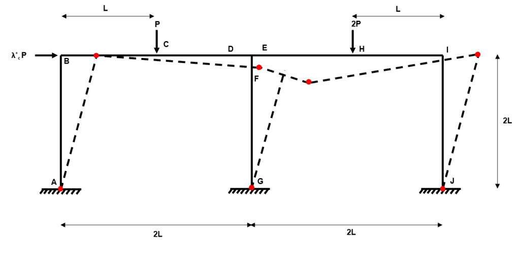
Fig 32. Example 3 composite mechanism 6
Composite Mechanism 7
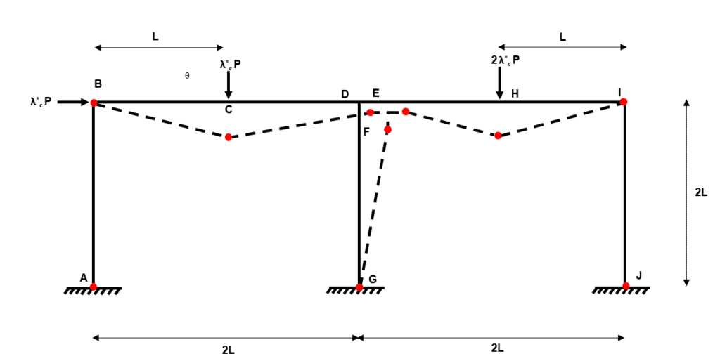
Fig 33. Example 3 composite mechanism 7
Composite Mechanism 8
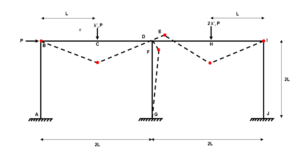
Fig 34. Example 3 composite mechanism 8
Composite Mechanism 9
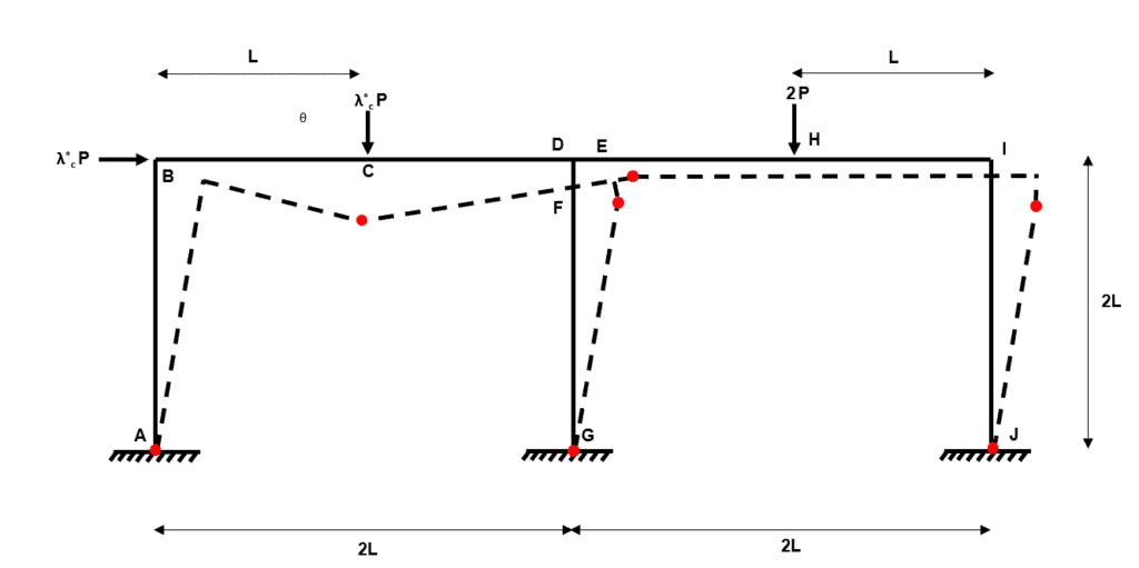
Fig 35. Example 3 composite mechanism 9
Composite Mechanism 10
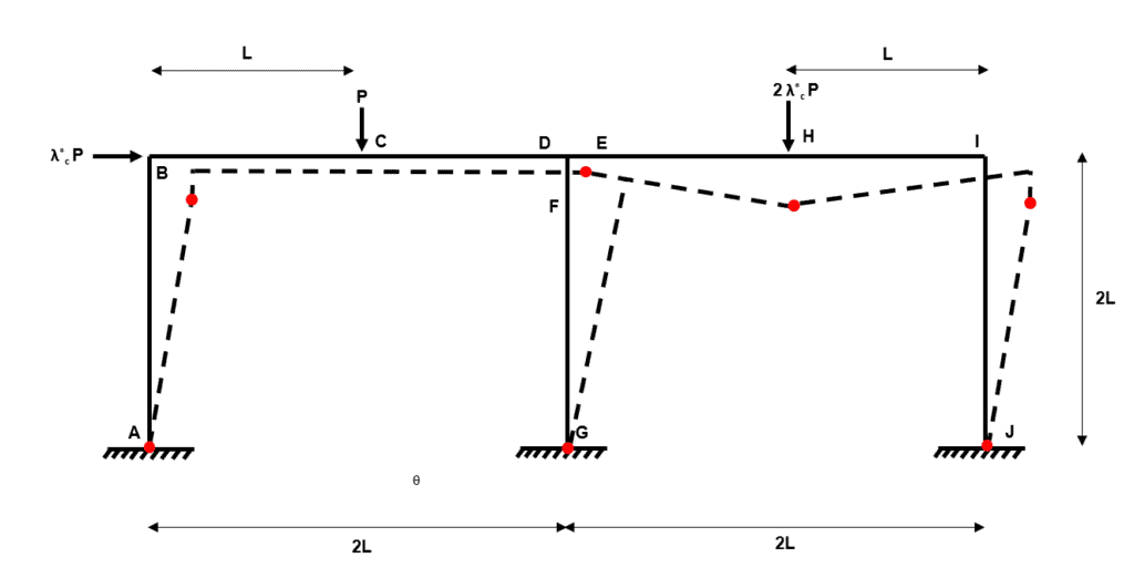
Fig 36. Example 3 composite mechanism 10
Composite Mechanism 11
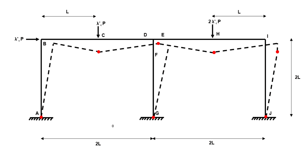
Fig 37. Example 3 composite mechanism 11
Step 5: For each collapse mechanism from (3) and (4), calculate
using the virtual work method**
and from this simple statement we can say:
Independent Mechanism 1
Independent Mechanism 2
Independent Mechanism 3
Independent Mechanism 4
Composite Mechanism 1
We can think of this mechanism as independent mechanism 1 plus independent mechanism 2.
Composite Mechanism 2
We can think of this mechanism as independent mechanism 1 plus independent mechanism 3.
Composite Mechanism 3
We can think of this mechanism as independent mechanism 1 plus independent mechanism 4.
Composite Mechanism 4
We can think of this mechanism as independent mechanism 2 plus independent mechanism 3.
Composite Mechanism 5
We can think of this mechanism as independent mechanism 2 plus independent mechanism 4.
Composite Mechanism 6
We can think of this mechanism as independent mechanism 3 plus independent mechanism 4.
Composite Mechanism 7
We can think of this mechanism as independent mechanism 1 plus independent mechanism 2 plus independent mechanism 3.
Composite Mechanism 8
We can think of this mechanism as independent mechanism 1 plus independent mechanism 2 plus independent mechanism 4.
Composite Mechanism 9
We can think of this mechanism as independent mechanism 1 plus independent mechanism 3 plus independent mechanism 4.
Composite Mechanism 10
We can think of this mechanism as independent mechanism 2 plus independent mechanism 3 plus independent mechanism 4.
Composite Mechanism 11
We can think of this mechanism as independent mechanism 1 plus independent mechanism 2 plus independent mechanism 3 plus independent mechanism 4.
Step 6: Select the mechanism that gives the lowest and check that
As per the other examples, we now have to check that the collapse mechanism satisfies the yield criterion within the uniqueness theorem. To do this we need to verify that the bending moment does not exceed at any location in the frame.
But wait….have you spotted the problem?
In both the previous examples we have identified collapse mechanisms where the number of hinges was equal to the degree of static determinacy , plus . Within plastic analysis we call this a complete collapse mechanism.
However, in example 3, our critical collapse mechanism has just three hinges, even though the degree of indeterminacy of the frame is 6. Within plastic analysis, we call this a partial collapse mechanism.
This creates a problem for us as we cannot use the method we implemented in example 1 and 2 to calculate a single redundant reaction to make the system determinate (allowing us to define the full bending moment diagram).
Instead we have to use a more counter-intuitive approach to determine a bending moment diagram which satisfies the yield criterion. Let us think about what we need to show…
To demonstrate adherence with the yield criterion we need to find _a set of statically admissible bending moments for which have $M. If we can do this then our collapse mechanism has satisfied the yield criterion.
Let us write four equations of equilibrium to represent the four independent mechanisms. As we are looking to identify bending moments across the entire frame, we will revert to express equilibrium in terms of bending moments at each of the 10 potential hinge positions identified in step 2.
Independent Mechanism 3
Independent Mechanism 1
Independent Mechanism 2
Independent Mechanism 4
We already know that because this defines independent collapse mechanism 2. It is clear though, that we cannot solve the above four equations simultaneously to determine the remaining unknowns.
So what can we do?
Well we have said that composite mechanisms are formed by combining independent mechanisms. We also found that composite mechanism 11 results in = 1.375, which is 10% higher than the critical load factor from independent mechanism 2.
We obtained composite mechanism 11 by adding all four of the independent mechanisms together. We can reflect this in a statical sense by adding together equations 1-4 above.
We know that Equation 5 breaks down when i.e. composite mechanism 11. We also know that at composite mechanism 11, …..which is very close to . So in fact, the bending moments across the frame for composite mechanism 11 will not differ very much at all from the bending moments across the frame in independent mechanism 2.
The next step requires a little extra thought. We know that the bending moments in composite mechanism 11 are very close to those within independent mechanism 2, this is shown by the small difference in . So let us set and within Equation 5 (which represents composite mechanism 11 remember!) equal to . We can do this because in independent mechanism 2, joint and have these values.
Ok, so we now have 5 remaining unknowns within Equation 5. We can arbitrarily choose values for four of these 5 (providing they are less than or equal to ).
So now we can take the 7 known values back to Equations 1-4 and solve for the remaining three unknowns , and …but we do this using because this maps the bending moment conditions of independent mechanism 2 onto composite mechanism 11!
Independent Mechanism 3
Independent Mechanism 1
Independent Mechanism 4
Let us collect all of our values for the collapse mechanism with
We can now draw the bending moment diagram for the entire frame.
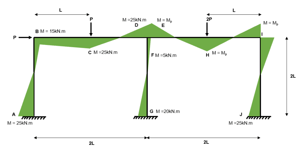
Fig 38. Example 3 bending moment diagram
The above section probably seems counter intuitive, so let us reflect on what we have done…and why…
We wanted to draw a bending moment diagram for independent collapse mechanism 2 but we found that we had 7 unknown bending moments in the frame. This occured because the collapse mechanism was partial rather than complete.
To overcome this problem we first observed that composite mechanism 11 is actually very close to independent mechanism 2. Next, we superimposed our known bending moments from independent mechanism 2 (joint and ) into composite mechanism 11.
Then, by assuming arbitrary values for four other moments within in the frame, we could solve for the remaining four bending moments using our original .
What we have ended up with is a set of statically admissible bending moments for which have $M This is one admissible set of bending moments within the frame, of which there are an infinite number of others (remember that we picked four values arbitrarily), but we only need to find one to demonstrate that the yield criterion is satisfied.
Therefore, .
7.0 Wrapping up
This brings us to the end of part two of this plastic analysis tutorial series. Part two has seen us apply our knowledge of plastic analysis theory to single and double-bay plastic frames. We have tackled three plastic analysis problems by applying a step-by-step approach to identify all of the possible collapse mechanisms.
We have then used the virtual work method to calculate the collapse mechanism which results in the lowest collapse load factor. Finally, and very importantly, we have determined the bending moment diagram for the entire frame to check that the yield criterion is satisfied.
I hope you have found the content useful and informative – if you did, share it with someone else who might also find it helpful!
Featured Tutorials and Guides
If you found this tutorial helpful, you might enjoy some of these other tutorials.
Using VIKTOR to Build a Shareable Truss Calculator App - Project Overview
Build a user-friendly analysis web app powered by OpenSeesPy and VIKTOR

Dr Seán Carroll
Understanding Tresca and von Mises Elastic Failure Theories
Go from the fundamentals of elastic failure theory to implementing section analysis in Python using sectionproperties

Julian Haudek
Truss Analysis using the Direct Stiffness Method
A complete introduction to the Direct Stiffness Method for truss analysis with a detailed numerical example

Dr Seán Carroll


