How to Calculate Reactions using Free Body Diagrams
![[object Object]](/_next/image?url=%2Fimages%2Fauthors%2Fsean_carroll.png&w=256&q=75)
The Fundamental Engineering Mechanics Series – Part 2
Welcome to part 2 of the Fundamental Engineering Mechanics tutorial series. This part will focus on how to use free body diagrams along with equilibrium equations to calculate support reactions. For the previous instalment in the series, go here. This series is for anyone just starting out studying engineering; first-year engineering students should find this series particularly helpful.
1.0 Free body diagrams
In this tutorial, we’ll cover free body diagrams and how to use them to evaluate the forces acting on a structure in equilibrium. A free body diagram is a diagram in which only the forces imposed on an object are shown. Free body diagrams are a simple tool to help us identify all of the forces that influence an object or structure. Typically, one of the first steps in analysing a structure is to sketch out its free body diagram, identifying all of the forces that must be considered in the analysis.
A simple example of a free body diagram for a mass resting on a horizontal surface is shown below.

Fig 1. Mass at rest on a supporting surface (left), simple free body diagram (right).
We can see the influence of gravity represented by the gravitational force , while the equal magnitude (opposite direction) reaction force imposed by the supporting surface is represented by . From this, we identify that there are only two vertical forces acting on the mass. This is a trivial example, but free body diagrams are particularly helpful when analysing more complex systems.
Consider a slightly more complex example of a pendulum swinging through the air.
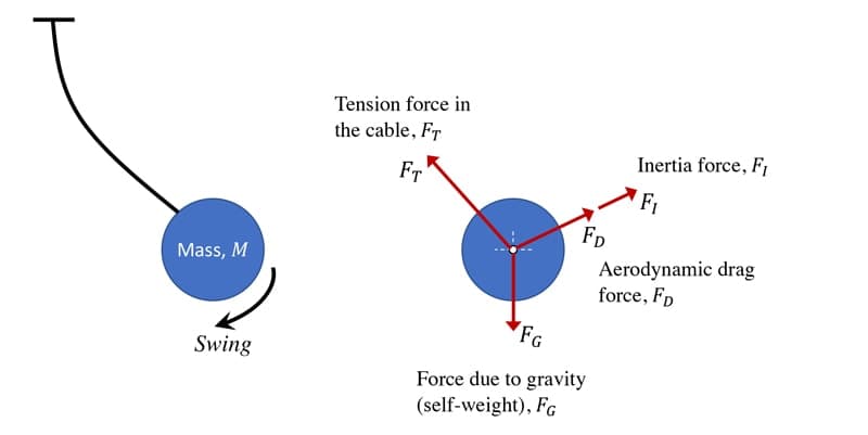
Fig 2. Free body diagram for a swinging pendulum (right).
In this case, we identify,
- The force due to gravity,
- The tension force in the suspension cable,
- The drag force due to the presence of air,
- The inertia force present due to the fact that the mass has an acceleration,
2.0 Equilibrium
An object is said to be in a state of static equilibrium if the sum of all forces and moments acting on the object are zero and the object is at rest. This is a direct result of Newton’s first law which states that a body remains at rest or moving with a constant velocity unless an unbalanced force acts upon it. From this we note that equilibrium can also apply to moving objects provided they are moving at a constant velocity. Such objects are said to be in a state of dynamic equilibrium. For now, we will just concern ourselves with objects in a state of static equilibrium.
If we again only consider forces and moments in a 2D plane (as we did for our discussion of equivalent systems in the previous tutorial), we can say that an object is in a state of static equilibrium if it satisfies the following three conditions,
Note here that we are considering the orthogonal components of forces experienced by an object separately. We could equally condense this and say simply that the sum of all forces on an object must equal zero,
If any of these conditions is not satisfied, the object will not be in a state of static equilibrium and will undergo a change in its velocity (i.e. it will experience an acceleration). We often use these three equations to identify unknown forces or moments in a system that is in a state of static equilibrium. As there are three equations we can solve for up to three unknown forces or moments. We’ll see this in action when we evaluate support reaction forces and moments below.
3.0 Supports and Reaction Forces and Moments
We saw above that an object resting on a horizontal surface, experienced a reaction force. Newton’s third law states that for every action there is an equal (magnitude) and opposite (direction) reaction. Therefore, the reaction force in this case is the force imposed by the support surface back onto the object. That reaction force is equal in magnitude to the gravitational force imposed by the object onto the surface.
As engineers it’s important that we understand the forces and moments our structures impose on their supports or foundations. In order to design foundations that will not experience unacceptable settlements for example, we need to know the forces and moments imposed by the structure. We also need to know what kind of support or restraint a particular foundation or support type will provide to our structure.
There are three common support/restraint models we employ to approximate real-world foundation behaviour.
3.1 Built-in / cantilever / encastre supports
If a structure is supported by (or restrained by) a built-in support, the structure will in theory be restrained against:
- vertical motion, i.e. a vertical reaction force can be generated at the support
- horizontal motion, i.e. a horizontal reaction force can be generated at the support
- rotational motion, i.e. a moment reaction can be generated at the support
This might be hard to visualise or understand right now, because we’re considering the support models in isolation. But supports and their associated restraints will make more sense when we consider them applied to structures below.
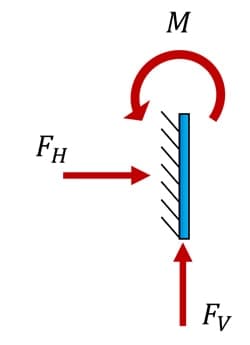
Fig 3. Built-in support with possible reactions.
3.2 Pin support
A pin support resists:
- vertical motion, i.e. it allows a vertical reaction to be generated
- horizontal motion, i.e. it allows a horizontal reaction to be generated
There is no resistance to rotation at a pin support and as such no moment reaction can be generated. This means that if a structure is connected to a pin support, the support itself will not provide any resistance to the structure rotating at that point.
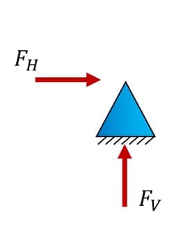
Fig 4. Pin support with possible reactions.
3.3 Roller support
A roller support resists linear motion in one axis only, i.e. it allows a reaction force to be developed in one axis only. The roller support shown in Fig 5 below would allow a connected structure to move freely in the horizontal direction but would restrain the structure from moving vertically. Like pin supports, roller supports do not provide any resistance to rotation.
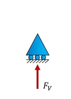
Fig 5. Roller support with a single possible reaction.
These three support types are idealised models of support behaviour. In reality no support behaves exactly according to these models. For example, if we plan to design a foundation that will stop our structure from rotating at that point, we will model the foundation as a fixed or built-in support. Our model will therefore not allow rotation and the simulated behaviour of our structure will reflect this absolute fixity – this does not mean that the actual foundation will have absolute rotational fixity!
On the other hand, if based on engineering judgement, we don’t believe the foundation, when constructed will offer significant resistance to rotation, we might model it as a pin or roller, which assumes zero rotational fixity. Again this is unlikely to match the actual as-built behaviour of the foundation. Consider how the three column supports pictured below would map onto our models of support.
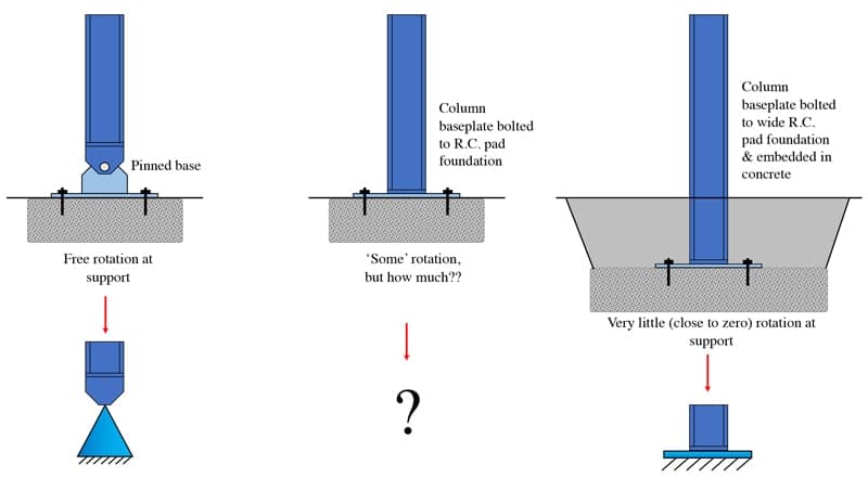
Fig 6. Three foundation support configurations (top three) and their potential models (bottom two).
The ability to appropriately map real-world behaviour onto our analytical models is a key part of becoming a competent engineer and is essential for any engineering analysis. An intuitive understanding for how well analytical models approximate real-world structural behaviour is something that comes with practice and experience.
Broadly speaking, a formal training in engineering will largely focus on developing knowledge of analytical models and how to manipulate them. During the first 3 to 5 years as a practicing engineer, the intuition for relating real-world behaviour to mathematical models is developed. This is one of the reasons why it typically takes a minimum of 4 or 5 years of post-graduation experience before professional chartership can be achieved.
One of the key takeaway messages from this section is that, although we’ve presented 3 neatly defined models of support, we must be careful in placing too much trust in the output of analytical modelling and recognise that actual foundations rarely adhere perfectly to this idealised behaviour.
3.4 Reaction Forces & Statical Determinacy
Once the supports for a structure have been appropriately modelled, we must determine the magnitude and direction of the various reactions developed at the supports. Remember, if our structure is subject to externally applied forces, reactions must be developed at supports to ensure the structure remains in a state of static equilibrium. Support reactions are developed directly in response to the loads applied to the structure (and any self-weight of the structure).
So, in order to identify support reactions we make the assumption that our structure is in a state of static equilibrium. This allows us to use the three equations of equilibrium above to solve for the unknown reactions.
Example #1
Consider the following beam subject to two point loads. The beam has a pin support at its left end and a roller support at its right end. This support configuration (pin and roller) is very common and a structure with this support configuration is often said to be simply supported.

Fig 7. Simply supported beam subject to two point loads.
Note the stability provided by this support configuration. The beam could not move horizontally (even if horizontal forces were applied) because it’s restrained in the horizontal direction by the pin-support at A. It can’t move vertically (ignoring deflection for now) because of the vertical restraint provided by the pin and roller at A and B respectively. Finally, it can’t rotate (again ignoring deflection between A and B for now) because of the ability of the vertical reactions at A and B to form a couple resisting any rotation.
Our task now is to calculate the values of the support reactions that are required to maintain this beam in a state of static equilibrium. This first thing we need to do is draw the free body diagram for the beam. As we said, this involves drawing the beam in isolated and then layering on all of the forces acting on the beam. In this case, it’s pretty straightforward as you can see below.

Fig 8. Free body diagram of the simply supported beam showing all forces.
We have three unknown reactions. We can consider these as potential reactions, since we don’t know yet whether any of them evaluate to zero. Since there are three reactions to identify, we can use the three equilibrium equations identified earlier. Let’s start by evaluating the sum of the forces in the vertical or y direction. We’ll assume forces pointing upwards are positive.
Next we can evaluate the sum of the moments about any point and let it equal to zero. If we take the sum of the moments about point A or B, then one of our unknowns will pass through the pivot point and be eliminated from our moment equation. So, taking moments about point A and assuming clockwise moments are positive,
Now, we still technically have one unknown reaction force, . By inspection, we can see that because there are no externally applied horizontal forces, no horizontal reaction develops in response, so, . This is why we said at the outset that we have three potential reactions. It turns out that in response to the applied loads, this structure only develops two vertical reactions. We can summarise our results with a final sketch of the structure.

Fig 9. Simply supported beam showing all support reactions.
Finally for this example, we can write some Python to perform the calculations for us. This is by no means essential, and could actually be considered overkill for this particular problem. But if you’re following this Fundamental Mechanics series and trying to pick up some Python along the way, this is a good exercise. It also gives us the ability to easily alter the input parameters and quickly evaluate the result without manually working through the calculations again.
Note that in the coded solution below we’re introducing a common programming structure known as an if/else condition. In the previous tutorial in the series, our Python programming just offered us the same functionality as a simple calculator. With this introduction of logic gates, your coding can now do much more than a simple calculator. Pay special attention to how the code below works.
#Define some variables
L = 15 #(m) Span of the beam between supports
P1 = 45 #(kN) Magnitude of first point load (left-to-right)
x1 = 3 #(m) Position of first point load from left hand support
P2 = 30 #(kN) Magnitude of second point load (left-to-right)
x2 = 9 #(m) Position of second point load from left hand support

#Calculate reactions
Vb = ((P1*x1) + (P2*x2))/L
Va = P1+P2-Vb

#Determine direction of Va
if(Va>0):
  dirA = 'upwards'
elif(Va<0):
  dirA = 'downwards'
else:
  dirA=""

#Determine direction of Vb
if(Vb>0):
  dirB = 'upwards'
elif(Vb<0):
  dirB = 'downwards'
else:
  dirB=""

#Output statements
print('1. The vertical reaction at support A is {one} kN '.format(one=Va)+dirA)
print('2. The vertical reaction at support B is {one} kN '.format(one=Vb)+dirB)
print('3. By inspection, the horizontal reaction at A is zero')
This code block outputs the following:
- The vertical reaction at support A is 48.0 kN upwards
- The vertical reaction at support B is 27.0 kN upwards
- By inspection, the horizontal reaction at A is zero
Example #2
For our next example, consider the same beam subject to the same loading but with the roller support at B removed and the pin support at A replaced by built-in or cantilever support. Now we have a classic cantilever beam.

Fig 10. Cantilever beam
Let’s start by evaluating the sum of the vertical forces,
We can see again by inspection that there is no horizontal reaction, therefore . Finally we can evaluate the sum of the moments about point A,
The negative sign here means that the assumed direction for the moment reaction in Fig 11 was incorrect and the reaction moment actually acts in the counter-clockwise direction. Whenever a moment of force evaluates to a negative number, this is telling us that the force or moment acts in the opposite direction to that initially assumed in the calculation. So we can restate the as a positive number and use an arrow to indicate its direction.
This makes sense when we image the influence of the applied forces on the beam would cause it to rotate clockwise about point A. therefore the reaction moment must act counter-clockwise to react to and resist this rotation of the structure. We can summarise our findings with a summary sketch.

Fig 12. Cantilever beam showing all support reactions.
Again, let’s code up a solution that automates the calculation process.
#Calculate reactions
Ma = -((P1*x1) + (P2*x2))
Va = P1+P2
Vb = 0

#Determine direction of Va
if(Va>0):
  dirA = 'upwards'
elif(Va<0):
  dirA = 'downwards'
else:
  dirA=""

#Determine orientation of Ma
if(Ma>0):
  dirMa = 'clockwise'
elif(Ma<0):
  dirMa = 'counter-clockwise'
else:
  dirMa=""

#Output statements
print('1. The vertical reaction at support A is {one} kN '.format(one=Va)+dirA)
print('2. The moment reaction at support A is {one} kNm '.format(one=Ma)+dirMa)
print('3. By inspection, the horizontal reaction at A is zero')
This code outputs the following:
- The vertical reaction at support A is 75 kN upwards
- The moment reaction at support A is -405 kNm counter-clockwise
- By inspection, the horizontal reaction at A is zero
Example #3
Next, let’s consider the same beam and loading but this time with a built-in support at A and roller support at B – a combination of the previous two cases. This configuration of beam and supports is ofter referred to as a propped-cantilever.

Fig 13. Propped-cantilever beam.
Our free body diagram reveals 4 unknown potential reactions, and . These are represented on the free body diagram below.

Fig 14. Propped-cantilever free body diagram.
Straight away we can see we might run into trouble here – we have 4 unknowns, but only three equations, but let’s follow our procedure and see where it takes us. Evaluating the sum of the forces in the vertical direction first yields,
Consider the sum of the moments about point A next,
So far, we haven’t been able to solve for any of our unknowns and we only have one more equation to use. Evaluating the sum of the forces in the horizontal or x direction gives us the familiar result, . So, we’re no closer to solving for or . This structure is referred to as statically indeterminate since the equations of statics alone are not sufficient to evaluate the unknown reaction forces. To solve for the reactions, we would need to use a more sophisticated analysis method, which we’ll leave for another day. This last example, simply demonstrates something we already know to be true; to solve for unknowns, we need independent equations.
4.0 Example Questions
Now that we have the basic workflow nailed down and understand the limitations of our approach, we can practice calculating support reactions for some more interesting structures and loading configurations.
4.1 Beam Example
Let’s evaluate the support reactions for the beam in Fig 15 below. Unlike the previous beams, this beam has a cantilever overhang to the right between B and E. However, the process of calculating the support reactions remains the same. As a side note, in a beam and support configuration like this where we have an overhang to one side, the portion of the beam between supports, A to B in this case, is often referred to as a back-span.

Fig 15. Beam example.
Note that the beam is subject to a uniformly distributed load (UDL) of meaning there are applied along every meter length of beam. We haven’t seen this load type yet but we deal with it in a fairly logical way; for the purposes of evaluating support reactions we can simply determine the equivalent point load.
This is obtained by calculating the total value of the UDL, in this case, . This equivalent point load will act at the mid-point of the UDL. So, the UDL is applied over which means its equivalent point load or resultant will act to the right of point D or to the right of B. Next we can sketch the free body diagram with the resultant force shown in green.

Fig 16. Free body diagram with UDL resultant force shown in green acting to the right of D.
At this point we’re ready to start evaluating the equilibrium equations. We start by evaluating the sum of the moments about point A,
Next we can evaluate the sum of the vertical forces to determine ,
By inspection we can state that the horizontal reaction is zero, since there are no externally applied horizontal forces. Now we can summarise these reaction forces on a final sketch of the structure, Fig. 17.

Fig 17. Beam example showing all support reactions.
For a little more Python practice, we can code up the solution following pretty much the same procedure as above.
#Define some variables
L1 = 11 #(m) Span of the beam between supports
L2 = 3 #(m) Right side overhang length
P1 = 80 #(kN) Magnitude of first point load (left-to-right)
x1 = 5 #(m) Position of first point load from left hand support
w = 25 #(kN/m) Magnitude of uniformly distributed load (UDL)
x_start = 9 #(m) Position of start of UDL
x_end = 14 #(m) Position of end of UDL
M = 40 #(kNm) Magnitude of applied moment

#Calculate reactions
Vb = ((P1*x1) + (w*(x_end-x_start)*(x*start+(x_end-x_start)/2)) + M)/L1
Va = P1-Vb+(w*(x_end-x_start))

#Determine direction of Va
if(Va>0):
  dirA = 'upwards'
elif(Va<0):
  dirA = 'downwards'
else:
  dirA=""

#Determine direction of Vb
if(Vb>0):
  dirB = 'upwards'
elif(Vb<0):
  dirB = 'downwards'
else:
  dirB=""

#Output statements
print('1. The vertical reaction at support A is {one} kN '.format(one=round(Va,1))+dirA)
print('2. The vertical reaction at support B is {one} kN '.format(one=round(Vb,1))+dirB)
print('3. By inspection, the horizontal reaction at A is zero')
This code block outputs:
- The vertical reaction at support A is 34.3 kN upwards
- The vertical reaction at support B is 170.7 kN upwards
- By inspection, the horizontal reaction at A is zero
4.2 Frame Example
For our final example, let’s consider something a little more interesting; a frame structure subject to both vertical and horizontal forces, Fig 18. Although the structure and loading might look a little more complex, identifying the reactions is really no more complicated than what we’ve done already.
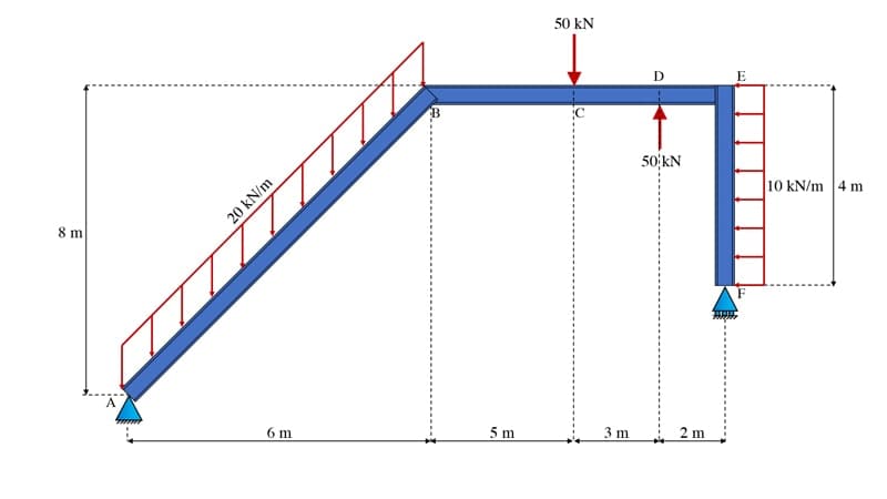
Fig 18. Frame example.
The first step is always the same – sketch the free body diagram. Since this structure has two UDLs, we’ll also evaluate and show the magnitude and location of their resultant forces. For the UDL applied on the left to the inclined beam element, we obtain the resultant magnitude by observing that the UDL is applied along an inclined length of . This yields a resultant of acting halfway between A and B. The UDL applied between E and F is easily determined to be acting horizontally to the left, halfway between E and F. Now we can sketch the complete free body diagram, Fig 19.
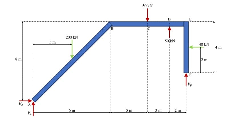
Fig 19. Frame free body diagram.
Once we’ve confirmed that there are no more than 3 potential reactions and the structure is statically determinate, we just rinse and repeat the same procedure we’re already familiar with. It doesn’t matter which equation we start with; I’ll start by evaluating the sum of the horizontal forces,
Moving swiftly on, we can evaluate the sum of the forces in the vertical direction,
Finally, evaluating the sum of the moments about point A,
As usual, we’ll summarise all of this on a sketch of the structure, Fig 20.
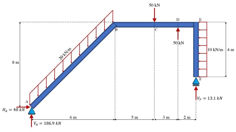
Fig 20. Frame showing support reactions.
5.0 Summary
This wraps up our discussion of free body diagrams, equilibrium equations and support reactions. There are really only a few important takeaway messages here to remind ourselves of:
-
Free body diagrams are incredibly helpful as we start to analyse more complex structures – make sketching out a free body diagram your first step in any structural analysis.
-
We introduced three support models – remember that they model idealised behaviour; either full fixity or zero fixity in the various degrees of freedom. This is rarely what we see in real structures so be aware of the limitations and simplifications inherent in your analytical modelling.
-
For the 2-dimensional planar structures we’ve analysed here, we only have three equations of equilibrium so we can only solve for three unknown reactions. If the support conditions result in more than three unknown reactions the structure is statically indeterminate and we need to break out bigger guns to analyse it (see stiffness method or virtual work analysis for example).
I hope you found this fundamental mechanics tutorial helpful. Keep an eye out for the next tutorial in this series. If you want to be notified when the next instalment is published, join the free Fundamentals of Mechanics course by signing up using the link at the top of this tutorial.
If you want full access to the complete EngineeringSkills course (and code!) library, for one low annual fee, consider subscribing to the All Access Membership or Lifetime Access Membership if you never want to pay for another course again :)
All Access Membership
Learn, revise or refresh your knowledge and master engineering analysis and design
Access Every Course and Tool
- Over 1140 lectures & over 234 hours of HD video content
- Access member-only 'deep dive' tutorials
- Access all downloads, pdf guides & Python codes
- Access to the StructureWorks Blender addon + updates
- Packed development roadmap of courses & tutorials
- Price Guarantee – avoid future price rises as we grow
- Priority Q&A support
- Course completion certificates
- Early access to new courses
Dr Seán Carroll's latest courses.
Featured Tutorials and Guides
If you found this tutorial helpful, you might enjoy some of these other tutorials.
A Complete Guide to the Flexibility Method for Beam and Frame Analysis
Learn how we can use the flexibility method to solve statically indeterminate structures.

Julian Haudek
Simulating crowd vibrations using the Duhamel Integral
Learn about the Duhamel Integral & how it can be used to simulate crowd-induced vibrations in Python

Dr Seán Carroll
Plate Girder Design to Eurocode 3
A step-by-step guide to the design of code-compliant steel plate girders.

Callum Wilson

