Forces, Moment of a Force and Force Systems
![[object Object]](/_next/image?url=%2Fimages%2Fauthors%2Fsean_carroll.png&w=256&q=75)
The Fundamental Engineering Mechanics Series – Part 1
Welcome to the Fundamental Engineering Mechanics tutorial series. This is part one in a multi-part series aimed at anyone just starting out in the study of engineering; first-year engineering students should find this series particularly helpful.
1.0 Forces, The Moment of a Force and Force Systems
As engineers, we spend much of our time analysing forces and their influence on the structures we design. So it’s a good idea at this stage to pin down exactly what a force is. Put simply, a force is the product of mass and acceleration.
Here on earth, all mass experiences an acceleration of approximately . So, a mass of experiences a gravitational force of,
The units of force are more conventionally expressed as Newtons (N) after Sir Isaac Newton. Thus is equal to . It’s important to understand the distinction between mass and force, e.g. a mass resting on a beam does not impose a force on the beam, but a force. Similarly, you may weigh , but you exert a force of about .
1.1 Force components and resultants
A force is a vector quantity. This means that it has both magnitude and direction. This is in contrast to a scaler quantity such as mass, volume, height etc. all of which can be completely described by a magnitude. Since force is a vector quantity, all of the usual rules and analysis techniques associated with vectors can be applied to forces.
All forces we will discuss in this tutorial occupy a 2-dimensional plane. This means that they can be completely described by two orthogonal (at right angles to each other) x and y components in a 2-dimensional axis system. This represents a reduction from full 3-dimensional Euclidean space. Once you understand the basic concepts for a 2-D force systems, expansion to 3-dimensions is straightforward.
Since 2-D forces can be represented as 2-D vectors, we can represent any force as the combination of 2 orthogonal components. Similarly, any number of forces can be represented as a single force resultant with specific magnitude and direction. Much of what we’ll do for the rest of this tutorial will involve:
- breaking forces up into their orthogonal components
- combining multiple forces to identify their force resultant
Consider the 100 N force shown below. Note that we have defined the force within a 2-D plane defined by the x and y axes. The force is applied at location . It has a magnitude of . Its direction can be indicated by stating that the force makes an angle of (counter-clockwise) with respect to the positive x-axis.
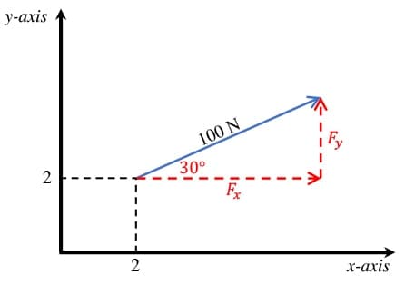
Fig 1. Force vector of orientated at an angle of counter-clockwise from the positive x-axis and its orthogonal components, and .
This force can be resolved into 2 orthogonal components, indicated above by and . Note that these can actually be any two orthogonal force vectors. For convenience, we’ve selected two orthogonal components parallel to the x and y axes. Simple geometry can be used to identify the magnitudes of and .
We can calculate the numerical values of and with some basic Python (or any other calculator you prefer).
#Define constants
F_mag = 100 # (N)Force magnitude
theta_deg = 30 # (deg) Angle force makes with positive x-axis
theta = theta_deg*math.pi/180 # (rads) Angle force makes with positive x-axis

#Calculate magnitude of orthogonal components
Fx_100 = F_mag*math.cos(theta)
Fy_100 = F_mag*math.sin(theta)

#Print output
print(f"Fx is {round(Fx_100,1)} N in the positive x-direction (to the right)")
print(f"Fy is {round(Fy_100,1)} N in the positive y-direction (upwards)")
Fx is 86.6 N in the positive x-direction (to the right)
Fy is 50.0 N in the positive y-direction (upwards)
We can evaluate the combined influence of multiple forces in the same way by breaking each one into its orthogonal components and recombining these components into a single force resultant. Consider the two forces shown below. The force is the same force evaluated above. We now need to determine the components of the force.
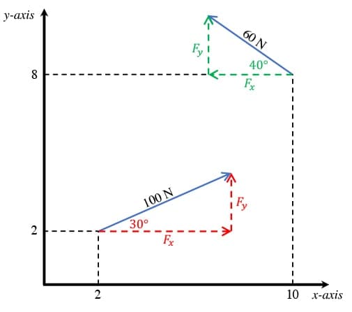
Fig 2. Two force vectors represented on the 2-D x-y plane.
#Define constants
F_mag = 60 # (N)Force magnitude
theta_deg = 40 # (deg) Angle force makes with negative x-axis
theta = theta_deg*math.pi/180 # (rads) Angle force makes with negative x-axis

#Calculate magnitude of orthogonal components
Fx_60 = F_mag*math.cos(theta)
Fy_60 = F_mag*math.sin(theta)

#Print output
print(f"Fx is {round(Fx_60,1)} N in the negative x-direction (to the left)")
print(f"Fy is {round(Fy_60,1)} N in the positive y-direction (upwards)")
Fx is 46.0 N in the negative x-direction (to the left)
Fy is 38.6 N in the positive y-direction (upwards)
The total horizontal force is obtained as the algebraic sum of the horizontal components of the and forces. Noting that the horizontal component of the force, acts in the opposite direction to the horizontal component of the force, .
Fx_total = Fx_100 - Fx_60
print(f"Fx_total is {round(Fx_total,1)} N")
Fx_total is 40.6 N
and represent two orthogonal force components and as such they can be represented by a single force vector, whose magnitude, and orientation, (measured with respect to the positive x-axis) can now be easily evaluated.
Evaluating these numerically,
#Magnitude
mag = math.sqrt(Fx_total**2 + Fy_total**2)
alpha = math.atan(Fy_total/Fx_total)
alpha_deg = alpha*180/math.pi
print(f"F_res a has magnitude of {round(mag,1)} N and an orientation of {round(ori_deg,1)} degrees relative to the positive x-axis")
F_res a has magnitude of 97.4 N and an orientation of 65.4 degrees relative to the positive x-axis
With reference to Fig. 3 below, the system of forces in the left hand axis system can now be replaced by the single resultant force in the right hand axis system. We’ll explore this concept of equivalent systems further below. The two force systems shown below are equivalent in terms of force. However, this doesn’t tell the full story. In order to obtain two completely equivalent systems, we need to also consider the moment or torque effect of each force.
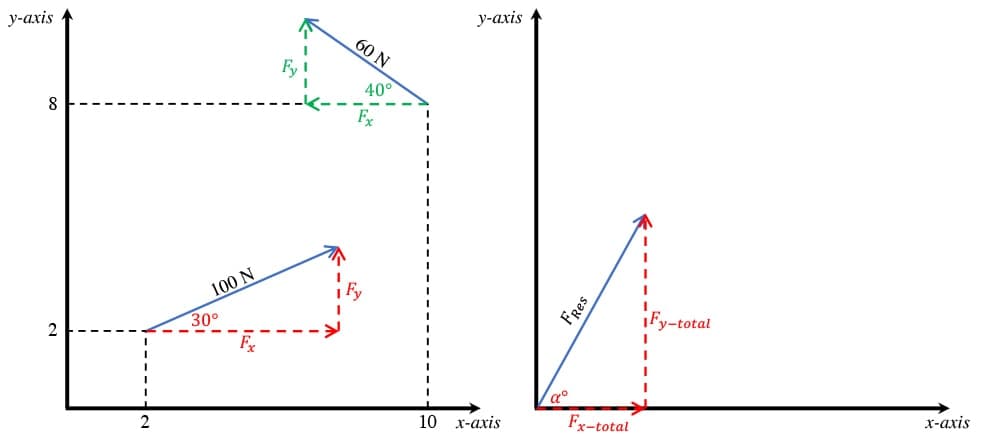
Fig 3. Force system with two forces (left) and a single resultant force representing their combined influence (right).
2.0 The Moment of a Force
The moment of a force is the twisting effect or torque that a force imposes or generates about a point. More specifically, the moment of a force is the product of force magnitude multiplied by a lever arm distance. The lever arm is the perpendicular distance between the line of action of a force and the point about which rotation occurs (or the torque is being calculated).
Consider holding a heavy box in your hands with both arms outstretched; this requires far more effort than if you hold the box close to your chest. This is because when your arms are outstretched, the force imposed by the heavy box generates a larger moment about the the point of rotation (your shoulder) than when you hold the box close to your chest.
For example, consider the force shown in Fig. 4 below, applied at a point in the x-y plane with coordinates . The force makes an angle of with the positive x-axis. By extending the force vector we obtain the line of action for this force. By projecting perpendicularly from the line of action to the origin, we obtain the lever arm for the force about the origin. Therefore this force generates a torque or moment, about the origin.
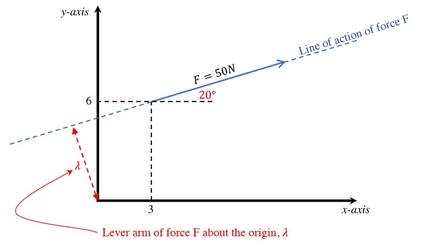
Fig 4. Force which generates a torque or moment about the origin.
We can intuit the sense of rotation as being clockwise. In other words, the force would tend to induce a clockwise rotation about the origin. If you have trouble identifying the sense of rotation, draw the origin point and force on a piece of paper with the paper restrained by a pin or needle through the origin. Use your finger to apply the force F and you will see the paper tends to rotate clockwise about the pin. You will only need to do this once or twice before you can visualise the sense of rotation a force induces about a point. The force will either rotate the paper clockwise or counter-clockwise and this will depend on the position and orientation of the force relative to the point about which moments are being calculated.
Now, in order to calculate the moment, we can use clever geometry to identify . However, there is an easier way to calculate the moment generated by . We can simply consider the moment generated by its orthogonal components. The horizontal and vertical components of , and are obtained as,
F_x = 50*math.cos(20*math.pi/180)
F_y = 50*math.sin(20*math.pi/180)
print(f"Fx = {round(F_x,1)} N")
print(f"Fy = {round(F_y,1)} N")
Fx = 47.0 N
Fy = 17.1 N
Now we can ignore the original force and only work with its orthogonal components, and . We can see quite easily that has a lever arm of while has a lever arm of (refer to Fig. 4). We can also recognise that would generate a clockwise rotation while would generate a counter-clockwise rotation (remember to use the rotating paper trick if you don’t see this). Thus we can evaluate the moment generated by by taking moments about the origin as follows,
la*fx = 6 #lever arm for the horizontal force component Fx
la_fy = 3 #lever arm for the vertical force component Fy
M = (F_x * la*fx) - (F_y * la_fy)
print(f"M = {round(M,1)} Nm")
M = 230.6 Nm
Remember, a moment is associated with a rotation, as opposed to forces that are associated with linear translations. So we define a moment as having either a clockwise or counter-clockwise sense of rotation. Note that in the above equation, we have implicitly assumed that clockwise moments are positive, while counter-clockwise are negative. Therefore the fact that the moment evaluates to a positive number indicates that the resultant moment, has a clockwise sense of rotation. If came out as a negative number, we would know that according to our sign convention, the moment has a counter-clockwise rotation.
By following the exact same logic, we can evaluate the combined torque generated by multiple forces about a point by evaluating the sum of the moments for each force in turn. We’ll discuss this further below.
2.1 Force couples
Two forces are said to form a couple when:
- they have equal magnitude
- have parallel lines of action
- act in opposite directions
For example, assuming and below have equal magnitude, they form a couple.
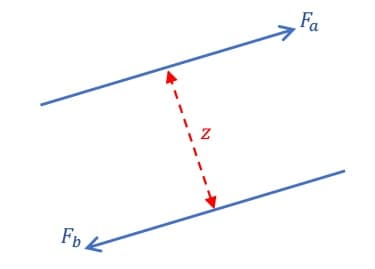
Fig 5. Two forces and forming a moment couple
A force couple generates a moment equal to the magnitude of one force multiplied by the perpendicular distance between their lines of action. So, the couple generated by and is,
We can see from the arrow directions that the couple pictured generates a clockwise moment. If the arrow directions were reversed the moment generated would be counter-clockwise. If you are having trouble visualising this, imagine a point of rotation half way along the red dashed line and ask yourself how these two forces would force the paper to rotate about this point.
Force couples appear frequently in engineering. You will find yourself evaluating the moment effect of force couples regularly. For now we simply want to define the concept.
3.0 Equivalent Force and Moment Systems
So far we have considered the vector properties of forces (components and resultants). We’ve also discussed the concept of torque or moments generated by a force about a specific point on the plane. Now we’ll bring these ideas together to evaluate systems of forces and moments and determine their resultant or equivalent systems.
Two systems of 2D forces and moments, and are said to be equivalent if three conditions are satisfied:
- The sum of all forces in the x-direction is equal in both systems
- The sum of all forces in the y-direction is equal in both systems
Note that the selection of the x and y-directions is arbitrary. Force equality along any two orthogonal directions can be evaluated. The x and y-directions are typically selected for convenience as they are also the axis directions for the system.
- The sum of the moments generated by all forces and moments in system A is equal to the sum of the moments generated by all forces and moments in system B
The practical value of identifying equivalent systems is that it allows us to represent multiple forces by a single resultant force that generates the same forcing and moment influence.
Consider again the force system we discussed previously,
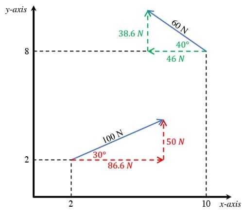
Fig 6. 2-D force system A.
In addition to evaluating the resultant force (completed above), we now need to determine the resulting moment. Evaluating the sum of the moments about the origin (again assuming clockwise moments are positive),
M = 86.6*2 - 50*2 - 46*8 - 38.6*10
print(f"The resulting moment about the origin is {round(M,1)} Nm")
The resulting moment about the origin is -680.8 Nm
The negative sign here indicates that the resulting moment is counter-clockwise according to our sign convention. Therefore, referring to the diagram below, we can say that the system of forces in system A is equivalent to the single force and moment in system B. In other words, system A has the exact same force and moment effect as system B.
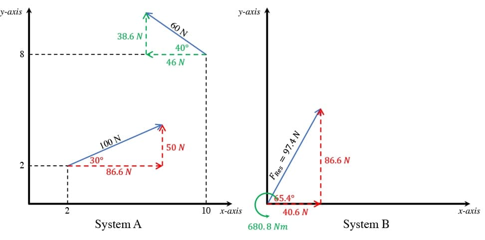
Fig 7. 2-D force system A and its equivalent system, B.
That pretty much covers the theory for this topic. At this point, you should try to work down through the example questions below. In each case, try to solve the question yourself first before watching the worked solution video.
Example
Replace the forces and moment shown in system A with an equivalent system consisting of a single force (at the origin) and moment (about the origin).
(Hint: Moments do not feature in a force summation equation but they do feature in a moment summation equation.)
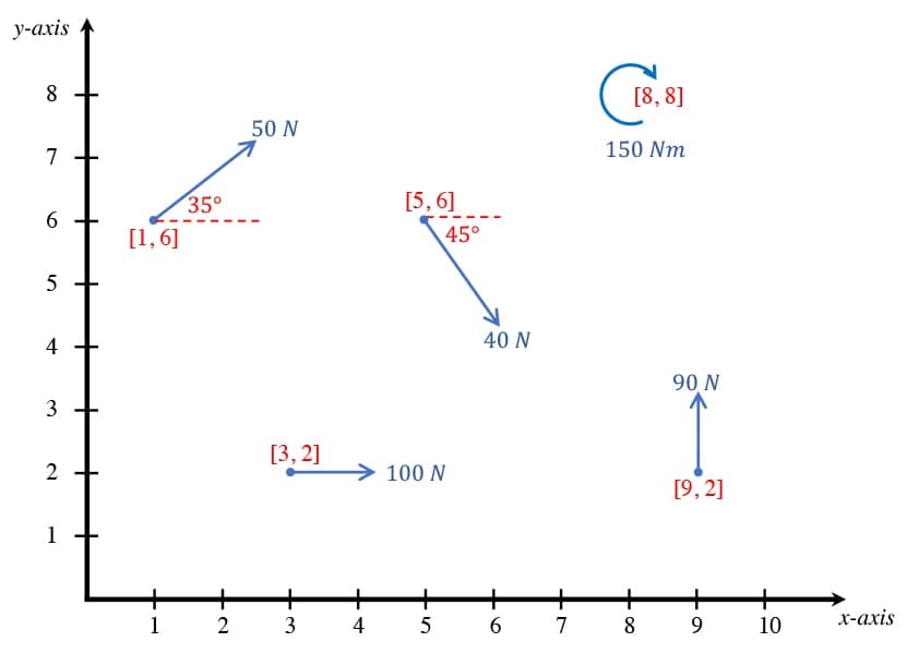
Fig 8. Example 1 force system.
Solution
The video solution to this question is covered at the end of the main lecture video at the top of this post.
Coded solution
#Calculate horizontal and vertical force component magnitudes
#(not considering direction yet, just magnitude)
F_Ax = 100
F_Ay = 0
F_Bx = 0
F_By = 90
F_Cx = 40*math.cos(45*math.pi/180)
F_Cy = 40*math.sin(45*math.pi/180)
F_Dx = 50*math.cos(35*math.pi/180)
F_Dy = 50*math.sin(35*math.pi/180)

#Moment magnitude (not considering sense of rotation yet)
M_E = 150

#Take moments about the origin (assume clockwise moments are positive)
M_o = F_Ax*2 - F_By*9 + F_Cx*6 + F_Cy*5 + F_Dx*6 - F_Dy*1 + M_E
print(f"The resultant moment is {round(M_o,1)} Nm")

#Evaluate the sum of the horizontal forces
Fx = F_Ax + F_Cx + F_Dx
print(f"The resultant horizontal force is {round(Fx,1)} N")

#Evaluate the sum of the vertical forces
Fy = F_By - F_Cy + F_Dy
print(f"The resultant vertical force is {round(Fy,1)} N")

#Evaluate the resultant magnitude
F_res = math.sqrt(Fx**2 + Fy**2)
print(f"The resultant force magnitude is {round(F_res,1)} N")

#Evaluate the resultant orientation
alpha = math.atan(Fy/Fx)*180/math.pi
print(f"The resultant force makes an angle of {round(alpha,1)} degrees with the positive x-axis")
The resultant moment is 68.2 Nm
The resultant horizontal force is 169.2 N
The resultant vertical force is 90.4 N
The resultant force magnitude is 191.9 N
The resultant force makes an angle of 28.1 degrees with the positive x-axis
Worked Example 1
With reference to the system of moments and forces below, replace the forces and moments shown in system A with an equivalent system consisting of a single force.
(Hint: Think about where you would like to place your single force in the replacement system.)
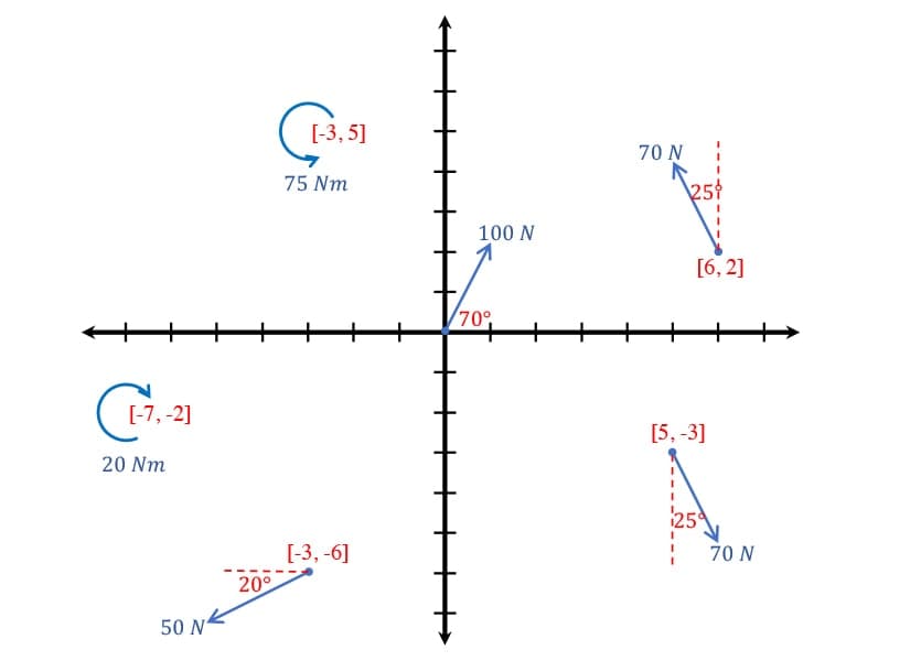
Fig 9. Example 2 force system.
Solution 1
Worked Example 2
With reference to the system of moments and forces below, determine the magnitude of the force, , for which the resultant moment and force for the system is zero.
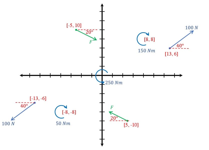
Fig 10. Example 3 force system.
Solution 2
Worked Example 3
With reference to the system of moments and forces below; this system must be replaced by a single force located along the vertical line at . Determine the location, magnitude and orientation of the replacement force.
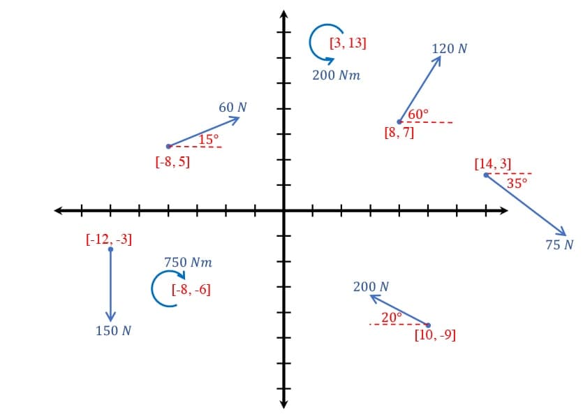
Fig 11. Example 4 force system.
Solution 3
That’s it for this tutorial. You should now have a good understanding of how to evaluate systems of forces and moments. In the next tutorial in this series, we’ll apply what you learned here and start to analyse the stability of simple structures. Don’t forget to join the course that accompanies this tutorial series to get access to all the notes and videos in one place. The course will expand as more tutorials in the series are published.
If you want full access to the complete EngineeringSkills course (and code!) library, for one low annual fee, consider subscribing to the All Access Membership or Lifetime Access Membership if you never want to pay for another course again :)
All Access Membership
Learn, revise or refresh your knowledge and master engineering analysis and design
Access Every Course and Tool
- Over 1140 lectures & over 234 hours of HD video content
- Access member-only 'deep dive' tutorials
- Access all downloads, pdf guides & Python codes
- Access to the StructureWorks Blender addon + updates
- Packed development roadmap of courses & tutorials
- Price Guarantee – avoid future price rises as we grow
- Priority Q&A support
- Course completion certificates
- Early access to new courses
Dr Seán Carroll's latest courses.


Featured Tutorials and Guides
If you found this tutorial helpful, you might enjoy some of these other tutorials.
How I Coded an Analytical Beam Calculator
How I built my analytical beam calculator, beamsolver.com and the challenges I encountered along the way

Vittorio Lora
Building a Parametric Frame Analysis Pipeline with OpenSeesPy and OpsVis
We’ll build a script to perform 2D elastic frame analysis and use OpsVis for fast visualisation of model behaviour

Dr Seán Carroll
Getting Started with Graphic Statics
Rediscover the link between geometry and load flow with graphical structural analysis techniques.

Prof Edmond Saliklis


