Structural Analysis Case Study
![[object Object]](/_next/image?url=%2Fimages%2Fauthors%2Fsean_carroll.png&w=256&q=75)
Structural analysis is the process of using mathematical and mechanical principles to determine the magnitude of internal forces that develop in a structure in response to external loading. When these forces have been determined, the corresponding stresses can be calculated. This allows the structure to be designed to withstand the applied loads.
A key task for the civil or structural engineer is carrying out structural analysis as the first step to designing a safe structure. The analysis process can be thought of as describing the path that external forces take as they ‘travel’ or are transmitted through the structure. This is called a load or force path and being able to determine these force paths is an essential skill.
In this tutorial we’ll demonstrate exactly how the structural analysis process works for a real world structure.
Structural Analysis of a Simple Bridge
To tease out the force path concept a little further, from here on we’ll base the discussion on the The Fort Atkinson Truss Bridge. Built in 1892, this is a classic example of what is known as a Pratt truss pattern. The Pratt truss was invented by Thomas Pratt in 1844 and is still a common form of truss. However it was first popularised in the design of railway bridges in the late 19th and early 20 century. A Pratt truss is identified by its diagonal members sloping down and towards the centre of the truss.
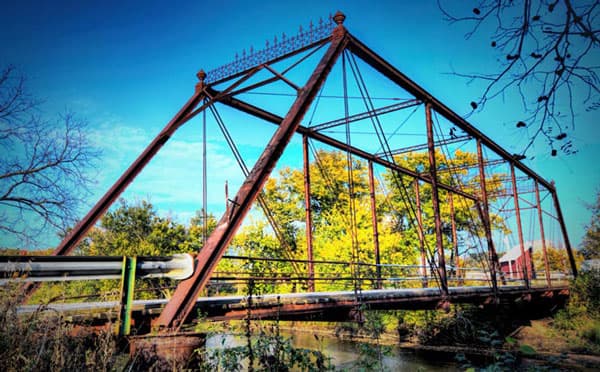
Figure 1a. Fort Atkinson Truss Bridge
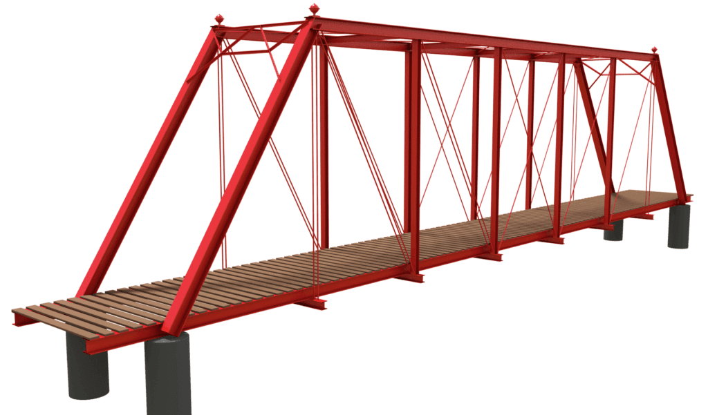
Figure 1b. Digital model of the Fort Atkinson Truss Bridge
Our bridge has a span of just over 40 meters and deck width of just under 5 meters. The bridge actually consists of 2 parallel Pratt trusses. This bridge has just enough complexity for us to demonstrate force paths and truss analysis without being so complex that we get buried in the details. For anyone who wants a detailed look at the bridge construction, take a look at this site which hosts plenty of survey photos.To get a feel for how the bridge is put together you can explore an interactive 3D model of the bridge below.
External forces applied to the structure
We’ll start by considering a simple scenario; a truck is parked at the centre of the roadway at the mid-span of the bridge. The truck weight is 16,500 kg, evenly distributed between the front and rear axles with the axles being 6.4 m apart. This will equate to an axle force of 16,500 kg 9.81 m/s2 = 161.9 103 N. So let’s say 81 kN per axle or 40.5 kN per wheel contact point (assuming 4 wheels).
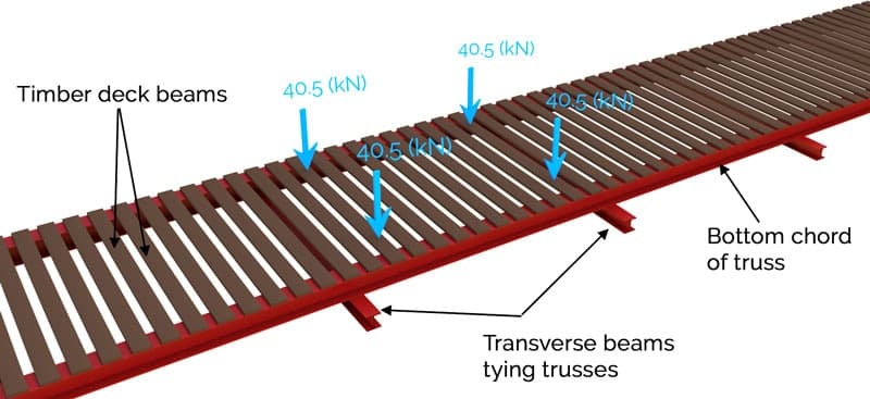
Figure 2. Forces transmitted from the wheel contact points into the deck beams
Our task is to work out how that force is transmitted through the structure back to the four supporting piers. We can logically say now that because the loading is symmetrically placed on the structure and because the structure itself is symmetrical, the support reactions at the piers should be 40.5 kN. Let’s do some basic structural analysis to see how that number arises. For the purposes of this discussion we will ignore the self-weight of the bridge and just track the imposed truck loading.
Force path from bridge deck to truss
Starting at the point of load application we can see that the wheels impose forces on the timber deck, Fig. 2. The deck beams span between the main bottom members of the trusses on each side of the bridge. In this case we have modelled the deck beams as simply supported beams. The pin and roller support represent the support provided by the bottom chords of the trusses. So we can say that the wheel loads are transmitted from the deck to the supporting trusses via bending and shear in the deck beams, as per Fig. 3.
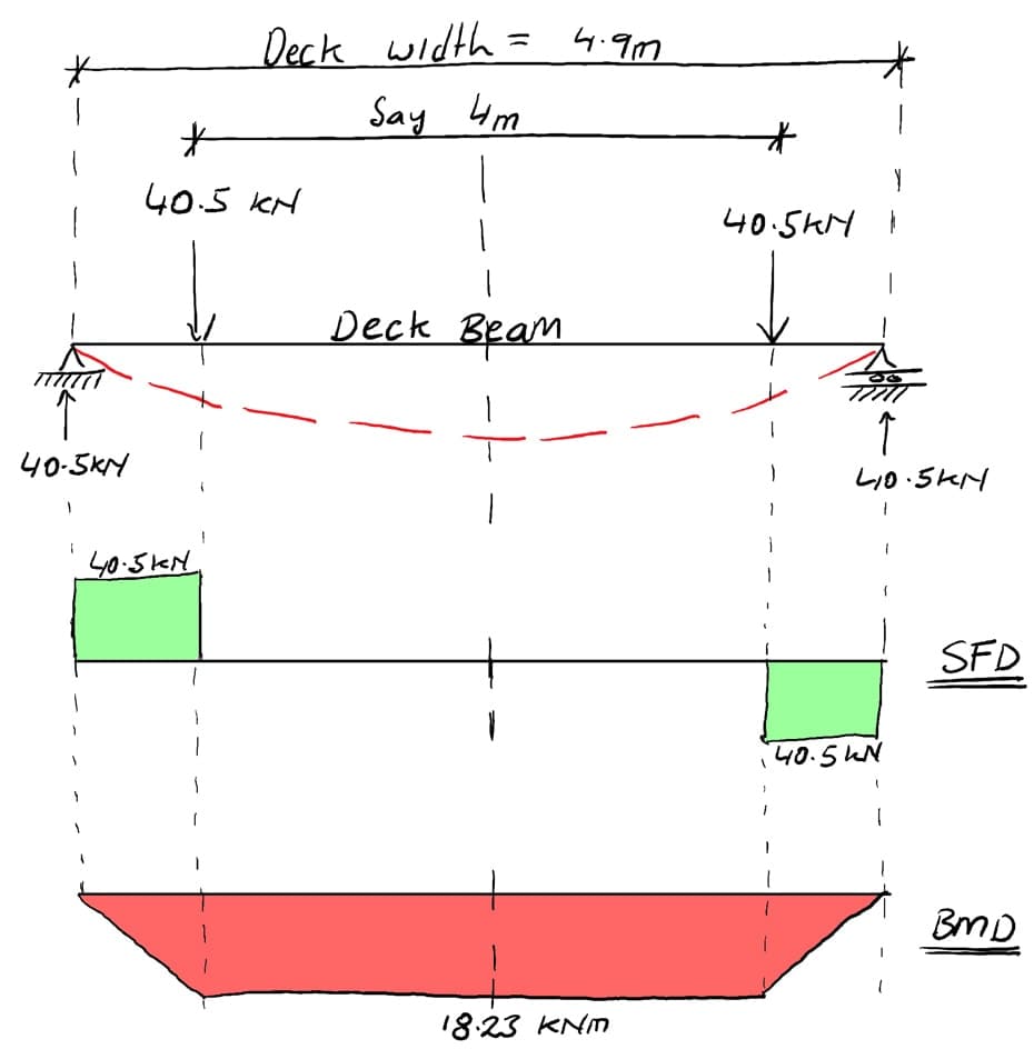
Figure 3. Bending moment and shear force in the timber deck beams due to the wheel loads
Because the deck beams are supported by the bottom chord of the trusses, and because the loading is symmetrical, 40.5 kN is transmitted into the bottom chord at each bearing point, Fig 4. With reference to Fig. 4, the force labelled ‘A’ represents the force imparted on the deck, by the truss chord whereas the force labelled ‘B’ is an equal magnitude, opposite direction force (with thanks to Sir Isaac Newton) representing the force imparted on the truss by the deck beam. This is force transmission in action.
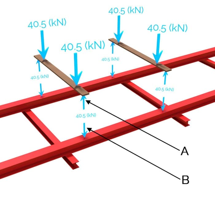
Figure 4. Force transmission from deck to bottom chord of truss
Now that we’ve clearly established how the wheel loads make their way into the bottom chords of the trusses, we need to pay attention to how the loads make their way into the nodes of the truss. Remember, we’re currently dealing with a case of inter-nodal loading. Before we can think about axial load transmission within the truss, we have to account for how the loads make their way into the nodes for onward transmission.
Force path from inter-nodal to nodal loading
You will have noticed that due to the positioning of the wheel loads, we have inter-nodal loading of each truss. As such, there will be bending moments induced in the bottom chords. Because the road deck bears directly onto the bottom chord of the truss, there will always be inter-nodal loading of the bottom chord. It would be important to consider this in a full design of these truss elements.
In order to model the influence of this inter-nodal loading on the bottom chord, it would be reasonable to model it as a continuous beam; as it essentially runs continuously over the top of the transverse beams positioned below the deck, Fig. 5. The bending moments determined from this analysis would be used to calculate normal stresses due to bending in the chord. These normal stresses would then be superimposed on top of the axial stresses arising from the truss analysis.
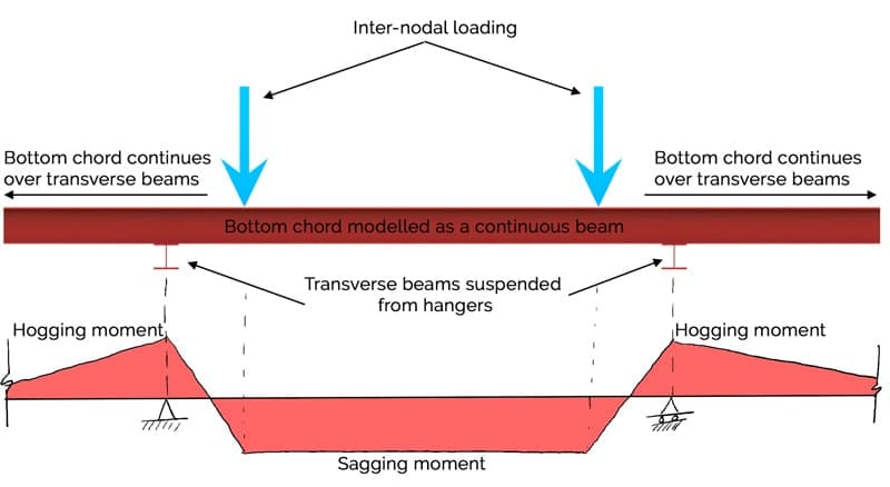
Figure 5. Modelling the bottom chord as a continuous beam to approximate the influence of inter-nodal loading.
It’s important to appreciate that the primary mechanism through which forces are transmitted back to the support piers is not via the bottom chord behaving as a continuous beam. This model was simply a means of approximating the bending stresses that develop due to inter-nodal loading. In terms of force transmission along the load path, the continuous beam model describes how the force is transmitted into the adjacent nodes of the truss. Ask yourself the question, ‘what supports the transverse beams onto which the bottom chord sits?’. Considering this it should become apparent that the complete truss (of which the vertical hangers and bottom chord are an integral part) is the primary structure that’s spanning the 40 m.
At this point we have described the path the load has taken and the mechanism of transmission from the deck into the nearest truss nodes. Note that the force transmitted into the adjacent nodes will not be exactly 40.5 kN, due to the continuous nature of the beam model. Nevertheless, this is a reasonable approximation for this analysis. Now we’re ready to focus on how the loading is transmitted through the truss itself. This involves working out the magnitude of internal force induced in each truss member. In order to do this we’ll employ two very common methods of structural analysis; the Method of Joints and the Method of Sections truss analysis methods.
Truss Analysis
First of all we need to nail down the precise geometry of the structure. We’ll do this by moving from a `realistic’ 3D representation of the truss to a simplified 2D visualisation onto which we’ll define the geometry, loading and support conditions. This simplified representation is our structural model used for the truss analysis, Fig. 6 below.
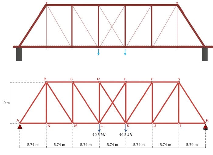
Figure 6. Reducing the ‘realistic’ representation of the structure (top) down to a working structural model (bottom). Note: members DK and EL are not joined.
Our first analysis task is to determine the support reactions. By inspection we can state that the potential horizontal reaction at support A is zero (because all external loads are vertical). Similarly, we can state by inspection that due to symmetry, the vertical reactions at A and H are 40.5 kN each.
At this point we can analyse each joint in turn using the Method of Joints; we’ll start with joint A. We will be evaluating the sum of the forces meeting at the joint. These forces can be resolved into two orthogonal (mutually perpendicular) directions allowing us to evaluate two equations of force equilibrium. Thus we have two equations from which we can determine two unknowns. So, using the method of joints we can only start at a joint that has a maximum of two unknown member forces. This is why joint A (or H) is a good starting point.
We isolate the joint by ‘cutting’ the members meeting at that joint. Making these cuts we ‘reveal’ the internal member forces, for now labelled as TAB and TAN where the T indicates we are assuming (until proven otherwise) that the forces are tension forces. A free body diagram of the joint is then evaluated by taking the sum of the forces in the horizontal and vertical direction and equating them to zero to reveal the unknown member forces. In the following analysis, note that basic geometry gives us the angles NAB = 57.5 degrees and ABN = 32.5. Now consider joint A, Fig. 7:
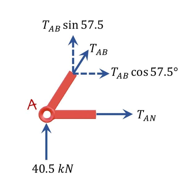
Figure 7. Free body diagram of joint A.
As mentioned above, we are initially assuming that the unknown internal member forces are tensile. This is also indicated by the force arrows pointing away from the joint in question. Taking the sum of the forces in the vertical direction and letting it equal to zero (assuming a sign convention with upwards forces positive):
The negative sign indicates our initial assumption of a tensile force was incorrect and TAB is actually a compression force. Thus the member between nodes A and B is experiencing 48 kN compression. Now considering the sum of the forces in the horizontal direction with forces to the right assumed positive:
In this case the positive number indicates that we were correct to assume a tensile force. Because the structure is both symmetrical and symmetrically loaded, we can conclude that the forces in member HI and HG are the same as those worked out for members AN and AB. Thus we only need to evaluate half of the structure in this example.
Moving on to joint N, Fig. 8, we can conclude by inspection that the force TNB = 0 kN and TNM = 25.8 kN tension.
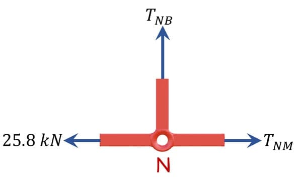
Figure 8. Free body diagram of joint N.
Now that we have solved members AB and NB, the only other joint with only two unknowns is joint B, Fig. 9. Evaluating the force equilibrium equations yields:
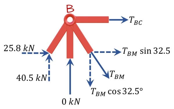
Figure 9. Free body diagram of joint B.
Moving on to joint M, Fig. 10:
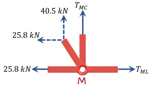
Figure 10. Free body diagram of joint M.
The only joint open for evaluation is joint C, Fig. 11. Evaluating the force equilibrium equations yields:
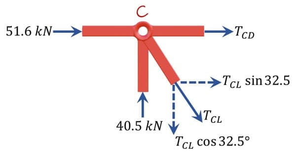
Figure 11. Free body diagram of joint C.
At this point it’s worth taking a look at our progress so far, mapped onto the structure, Fig. 12. We can see that joints D and L both have three unknown member forces. Therefore isolating either joint would result in too many unknowns given the available equilibrium equations (2). The method of joints has taken us as far as it can. At this stage we need to consider an alternative method of truss analysis known as the Method of Sections.

Figure 12. Internal member forces evaluated using the method of joints.
Instead of isolating a single joint, the method of sections involves us making an imaginary cut through the entire structure. In doing so, we reveal the internal member forces in the members our plane cuts through. We can then evaluate equilibrium of the sub-structure created by the cut. This method of structural analysis brings into play a third equilibrium equation; now we can take the sum of the moments about any point in addition to considering vertical and horizontal force equilibrium. Since the structure is in a state of static equilibrium, the sum of the moments (just like the forces) must equal zero. So we now have three equations of statics at our disposal. The key thing is that our plane cannot cut through more than three unknown members. Making an inclined cut as shown in Fig. 13 should allow us to determine the internal forces in members LD, LE and LK.
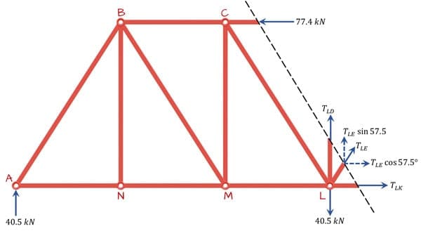
Figure 13. Sub-structure produced by the cutting plane, revealing three unknown member forces.
Evaluating the sum of the moments about point A and assuming clockwise moments are positive yields:
Equating the sum of the vertical and horizontal forces to zero yields:
Our three equations of equilibrium have yielded only two independent equations! As such we cannot solve for our three unknowns in this case. We can say that our structure is statically indeterminate. This is an important concept that we’ll discuss further below. At this point it appears that we are at an impasse! In most cases however (when our structure is statically determinate), the method of sections will yield 3 independent equations from which we can derive our three unknown member forces.
Statical Determinacy
We’ve seen above that there are some conditions that apply to our ability to analyse a truss; to use the method of joints we need joints with 2 or less unknowns and for the method of sections we can accommodate no more than 3 unknowns. If these conditions are not met, we will not be able to use statics to determine the forces in the structure, i.e. it is statically indeterminate. As we’ve seen above, even if we can generate an apparently suitable section that only cuts through three unknowns, we may still run into trouble. So we need a more rigorous method for establishing the statical determinacy of our structures.
We can employ a simple equation that allows us to test the determinacy of a truss. Let’s say that for each node, we have two possible equations, we’ll let denote the number of nodes in a structure. Therefore we have access to possible equations.
If the the number of unknowns is equal to the number of members, denoted by , we might say that once our truss is statically determinate. But remember, we also have three unknown reactions to solve for. So actually our condition for determinacy is . If this is the case we can solve for all member forces and our structure is statically determinate. If Consider the truss above. It has 14 joints (A to N), therefore for statical determinacy, it should have exactly members. It actually has 26! This confirms for us that it is indeed statically indeterminate. In fact we can say that it is statically indeterminate to 1 degree. Therefore, to analyse this structure using the equations of statics we would need to remove 1 member. Note that we’re not generally in the habit of just throwing away members – so a finding of statical indeterminacy would usually trigger us to explore alternative solution methods.
However, for the purpose of discussion; we can see the result of first removing member EL (below-top) and then alternatively, removing member DK (below-bottom). In either case, we could quite easily complete our analysis by making a vertical cut between D and E and evaluating either sub-structure created by the cut. It’s worth noting that in both cases, the structure would remain perfectly viable and stable.
The fact that in both analyses, the central members carry no force, makes it tempting to consider completely removing these members. After all if they carry no force, why do we need them? Remember, we are only considering one possible load combination here. Under the action of these symmetrical applied loads, these members carry no force, but if say, the 40.5 kN at L was removed, then the members currently carrying zero force would indeed develop internal member forces.
As it happens, in the case of this particular truss with this symmetrical load combination, because so many of the members carry zero force, if we knew this ahead of time, we could remove one of them for the purpose of our analysis, rendering the structure statically determinate and solvable. However, there was no way for us to determine what members had zero force using just the equations of statics. When analysing a complex truss, it is a good idea to test its determinacy first, before embarking on a laborious hand analysis.
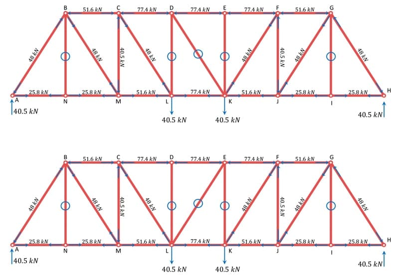
Fig 14. Truss with a single redundant member removed. Member EL is removed in the top image and member DK is removed in the bottom image.
Upon further analysis of the complete indeterminate structure using an alternative solution method (direct stiffness method for example), we can confirm that, for the loading shown, both DK and EL are in fact zero force members, Figure 15. So, let’s proceed on that basis.
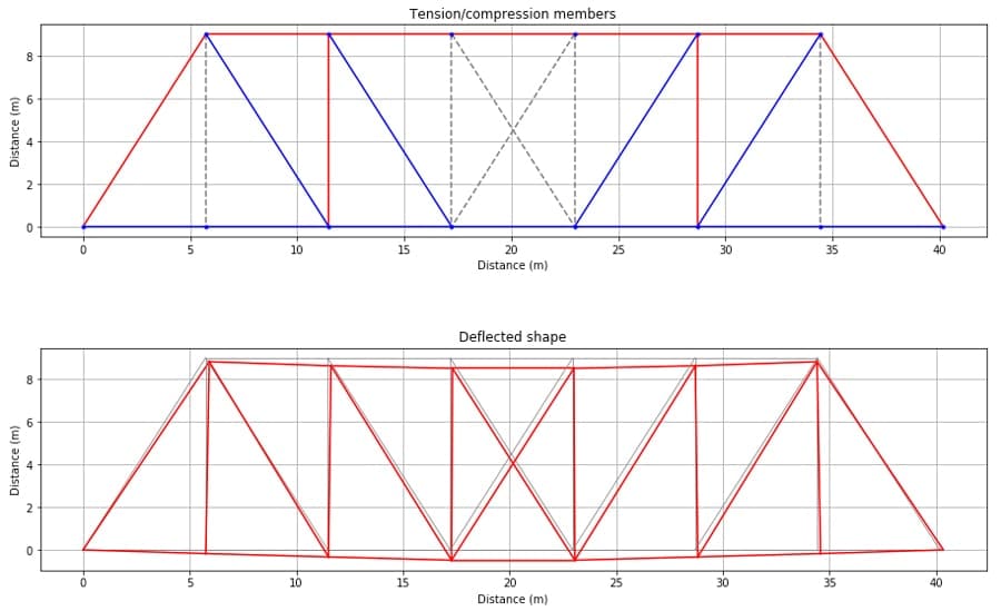
Fig 15. (Top) Axial force diagram for the complete indeterminate truss structure. Members in tension are shown in blue, members in compression are shown in red and zero force members are dashed grey. (Bottom) Deflected shape for the structure (side benefit of direct stiffness analysis method!). Build your own stiffness method analysis programme by taking the course below.
The Direct Stiffness Method for Truss Analysis with Python
Build your own finite element truss analysis software using Python and tackle large scale structures.
After completing this course...
- You’ll understand how to use the Direct Stiffness Method to build complete structural models that can be solved using Python.
- You’ll have your own analysis programme to identify displacements, reactions and internal member forces for any truss.
- You’ll understand how common models of elastic behaviour such as plane stress and plane strain apply to real-world structures.
Truss Design
It’s worth saying that before any design could proceed, a much more detailed loading analysis would be undertaken in reality. For example, under different loading conditions (position and magnitude of loading) the members that have zero internal force in this analysis would develop internal forces. Identifying the range of expected internal forces (and therefore stresses) would be the main objective of a robust loading analysis, a precursor to full truss analysis.
Now that we have more insight into how this bridge structure works, it’s worth taking a second look at the actual bridge to see if we can identify the reasoning behind some of design decisions.
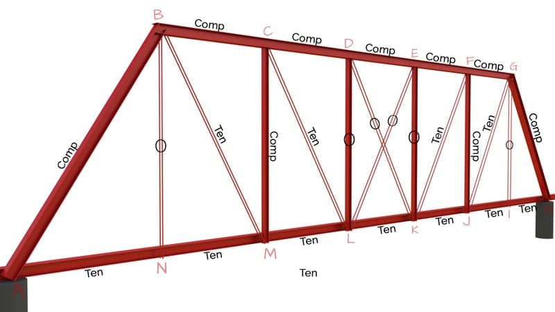
Figure 16. Internal axial forces in the truss with tension, compression and zero force members indicated.
With reference to Fig. 16 above, we notice the following:
- The four inner vertical members (CM, DL, EK, FJ) are stockier than the outer verticals and the diagonals. More specifically we would say they have a higher flexural rigidity or resistance to bending. This is because they resist compression forces and therefore must be capable of resisting not just direct compression stress but also buckling. Buckling is an instability whereby a compression member can fail (buckle) at a load below its ultimate axial load capacity. Buckling resistance is dependent on both the flexural rigidity of the member and a parameter known as effective length which is a function of both the length of the member and the degree of rotational restraint at its ends. I will talk more about buckling in another tutorial, but suffice to say the vertical members identified are stockier in order to resist failure due to buckling.
- The outer vertical members are much more slender than their vertical neighbours. We can see that for this load arrangement, there is no force in these members. However, for another load arrangement, say if a truck wheel was positioned in line with node N; we could expect to see an axial force develop. However, provided the loading is due to gravity (i.e. always downwards in direction), compression will never develop in these members, only tension. Therefore there is no need to resist buckling, only direct tension. As a result, the members can be much slimmer.
- The same reasoning applies to the sizing of the diagonal members. They will always be in tension, and can therefore be much slimmer that any member that must also resist buckling.
- The top chord is in compression while the bottom chord is in tension. The magnitudes of the axial loads increase as we move towards the centre of the truss. This is typical and exactly as we would expect for a simply supported truss. These members will usually be the largest, and sure enough that is also the case with the Fort Atkinson truss; remember, the top chord members must not buckle, while the bottom chord members must resist the added normal stresses due to bending induced by the loading on the deck (discussed earlier).
So hopefully you now have a clearer understanding of truss analysis, the design decisions that follow and how external forces make their way from the point of application on the deck, all the way back into the bridge pier foundations. Once you have this insight, you can start to get inside the minds of the engineers who designed this bridge over 120 years ago.
Structural Analysis and Lateral Forces
So far our structural analysis has focused on how vertical forces are transmitted from the point of application, through the structure, and back down to the ground via the foundations. Before we can wrap up the analysis of this bridge, we need to think about the lateral stability of the structure. It’s not sufficient to simply design a path for vertical loads to make their way into the foundations, we have to think about how any lateral loads would be transmitted through the structure also.
It’s true that in most cases the predominant loading direction will be vertical, however lateral loads can arise from a number of sources. The most obvious one is wind, probably followed by dynamic earthquake loading. Wind action on bridges is a fascinating topic in its own right, however wind won’t have a significant impact on this particular bridge as there’s not much surface area to ‘catch’ the wind. Nevertheless, we still have to ensure the structure is robust. So wind or no wind, we need to tie the structure together and facilitate a safe transmission of loading in the out of plane direction (perpendicular to the span direction in the plane of the deck). In this post, we’ll carry out a brief qualitative (without numbers) structural analysis to demonstrate the load path providing lateral stability.
Looking at this bridge we can see a number of features designed specifically to provide lateral stability. To facilitate the discussion lets assume a horizontal point load is applied half way up one of the vertical members. We can think of the vertical members (on the side of the bridge) as spanning between the deck and the top of the truss, let’s call it the ‘roof’ for brevity. Thus the applied force will be distributed via bending and shear equally into the roof and deck, as shown by the two blue force arrows in Fig. 17 below.
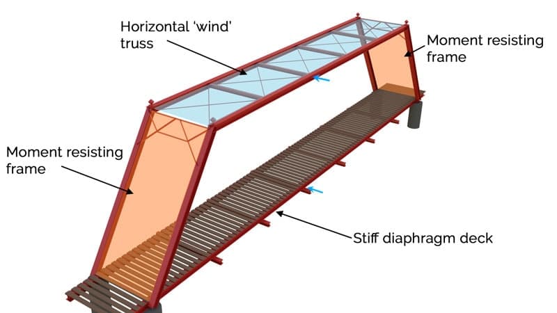
Figure 17. Lateral stability scheme identifying the main components.
In Fig. 18 we can see that the wind truss in the roof (blue) spans between the frames (orange) at each end of the deck. These frames transmit the high level loading via bending and shear back down into the foundations. In this way, the roof (blue) and moment frames (orange) act together to provide a unified (side facing) ‘portal’ frame into which lateral loads can be transmitted and carried back into the foundations.
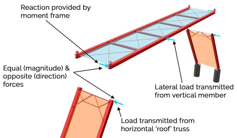
Figure 18. Force transmission between the roof truss and moment frames.
Taking a closer look at the wind truss in the roof we notice that all of the members are quite slender indicating they’re only designed to resist tension forces (they would buckle under any significant compression force). Looking at Fig. 19 we can see how the forces are transmitted through the truss.
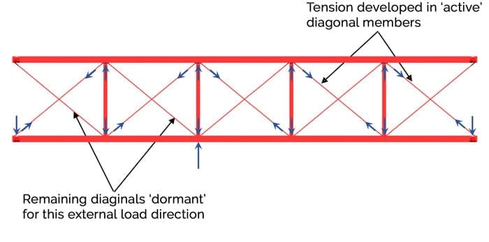
Figure 19. Load transmission through the wind truss indicating active and dormant diagonal members.
For the purpose of our structural analysis exercise, let’s say that the external loading is coming from the south (bottom of the figure). In this case tension is developed in half of the diagonal members as shown. In theory, compression forces would develop in the opposite diagonal members (shown with no force arrow). In reality they are so slender that they will simply sag under their own weight and continue to deflect under the action of any compression force. But, the existence of the tension members stops this from happening. The net result is that the tension members are facilitating force transmission through the truss and at the same time, protecting the opposite diagonal members from excessive deflection due to compression. The clever thing about this strategy is that if the external forces come from the opposite (north) side, the roles are reversed; the currently dormant diagonals go into tension, allowing the currently active members to simply sag under their own weight with negligible internal force developed. Any time you see cross bracing with very slender members, this is the strategy being employed.
The wind truss successfully channels forces to each end of the bridge. The next step in our structural analysis is to work out how the forces get down to the foundations. This is achieved using the framing action of the end-bay frames, Fig. 20. The term ‘framing action’ refers to the frame’s ability to resist lateral loading by developing internal moments and shear forces. The triangular arrangement of smaller members across the top of the frame in Fig. 20 are provided in order to stiffen the frame against lateral sway. Remember, the magnitude of lateral loads on the structure is expected to be small so we would not expect to see very stocky members provided. Note the ‘lever arm’ marked in Fig. 20. The larger this distance, the smaller will be the stresses developed as a result of the sway moment. Remember, moment force lever-arm.
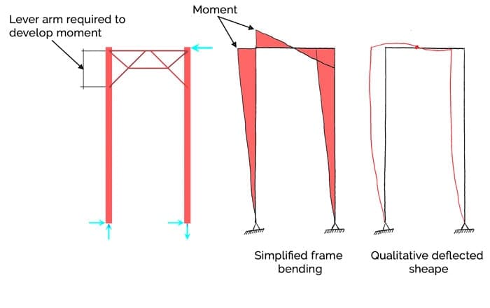
Figure 20. Lateral resistance provided by ‘sway’ frames.
The last component of the lateral stability system to investigate is the bridge deck. The load that was transmitted into the deck is carried directly back to the foundations via the deck acting as a stiff diaphragm or plate. Cross bracing is not required in the deck (the way it’s used in the roof) because the deck timbers provide more than adequate stiffness to the deck in the out of plane direction. In the out of plane direction, we can think of the deck as a simply supported beam spanning 40.2 m with a depth of 4.9 m (deck width), Fig. 21. This would give a very favourable span/depth ratio of 8.2, well within the comfort zone for a simply supported structure.
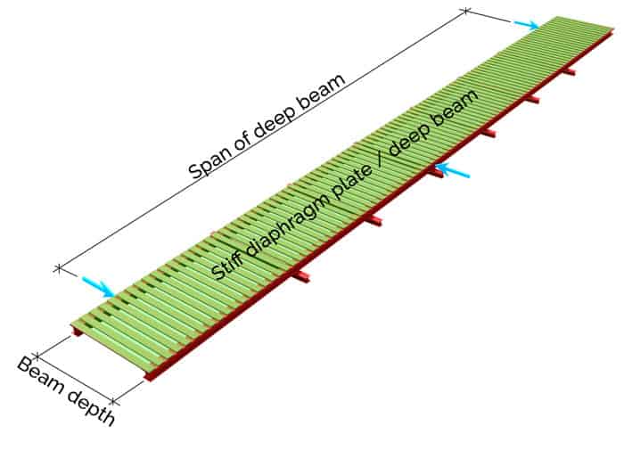
Figure 21. Diaphragm/deep beam bending of the deck, stiffened by the deck timbers.
That pretty much wraps up our structural analysis of the Fort Atkinson Truss Bridge. Hopefully you found this case study structural analysis helpful. Why not try it again yourself with another structure. The next time you see an interesting structure, be it a bridge or building, take some time to dissect it and carry out a structural analysis. Try to work out just how it’s resisting the effects of gravity and all of the other elements nature throws at it! Spend enough time doing this and you’ll start to develop a strong intuitive understanding of structural analysis and structural behaviour. To help you along the way, why not take a look at one of my online courses, Fundamentals of Structural Analysis is a good starting point. If you’re ready to move beyond the basics, take a look at the course below on building a 2D truss analysis programme in Python – no coding experience required!
ONLINE TRUSS TOOLBOX 🛠️
Try our free truss analysis toolbox for calculating reactions, axial forces and deflections. A handy tools for students and professional engineers.
Dr Seán Carroll's latest courses.

Featured Tutorials and Guides
If you found this tutorial helpful, you might enjoy some of these other tutorials.
Understanding Structural Dynamics and Inertia
How and why dynamic analysis is performed instead of simpler static analysis

Dr Seán Carroll
