Plastic Analysis and Plastic Collapse – A Complete Guide – Part 1
![[object Object]](/_next/image?url=%2Fimages%2Fauthors%2Fcallum_wilson.jpg&w=256&q=75)
Welcome to part one of this two-part tutorial series, which is focussed on plastic analysis methods also knows as plastic collapse analysis. This first part builds upon what we covered in a previous tutorial on plastic hinge formation in beams. If you have a chance, it would be worth refreshing your understanding of plastic hinges and plastic section capacity before diving into this tutorial.
By the end of part one:
- you will be comfortable performing plastic analysis
- you will understand why plastic analysis is important for Engineers
- and finally, you will have the tools to calculate collapse load factors for determinate and indeterminate beams.
All Access Membership
Learn, revise or refresh your knowledge and master engineering analysis and design
Access Every Course and Tool
- Over 1140 lectures & over 234 hours of HD video content
- Access member-only 'deep dive' tutorials
- Access all downloads, pdf guides & Python codes
- Access to the StructureWorks Blender addon + updates
- Packed development roadmap of courses & tutorials
- Price Guarantee – avoid future price rises as we grow
- Priority Q&A support
- Course completion certificates
- Early access to new courses
1.0 Why is plastic analysis important?
Before we introduce plastic analysis, let's think about our current understanding of structural analysis methods. In the majority of cases when you have found yourself conducting structural analysis, you will most likely have been performing a linear-elastic analysis. So what do we mean by this?
Linear elastic analysis deems failure to occur when any part of any structural member within the structural system reaches its yield stress. For example, if we were analysing a simply-supported beam, we would ascertain the maximum bending moment along the beam and then use the engineer's bending theory to determine the normal stress at the extreme fibres.
If this stress is less than the yield strength of the material, then we can say that the beam satisfies the bending requirements. Using elastic analysis we can quite happily check all of the members within our structural system to ensure that internal stresses do not exceed the yield strength....simple right?!
But wait...we need to ask ourselves if elastic analysis is really a suitable model for the actual structural behaviour. As discussed in a previous tutorial, many structural materials exhibit plastic behaviour. Plastic behaviour is characterised by an increase in strain at a constant value of stress (the yield stress).
So, using our understanding of plastic behaviour, we know that certain structural materials can accept loads which are higher than there 'yield loads' because they are able to utilise the section's plastic capacity.
Ok, so if our structural member is actually able to accept loads higher than predicted by a linear-elastic analysis, then does this mean that we are underestimating the real failure load of our structural system when we use linear elastic analysis?!....well, yes.
In reality, the actual failure load of certain structural systems can be more accurately predicted using plastic analysis rather than elastic analysis. It is important that we can accurately determine the actual failure load of structures because this allows us to make informed and materially efficient decisions about member sizes and factors of safety. We will go on to discuss which structural systems are most suitable for plastic analysis a little later.
2.0 Plastic analysis checklist
Prior to undertaking plastic analysis, we must first complete the following checklist to ensure that our structural system is suitable for plastic analysis techniques.
2.1 Can the material behaviour be suitably modelled as elastic-perfectly plastic?
If the material which we are considering cannot reasaonably be assumed to behave in an elastic-perfectly plastic manner, then we should not be using plastic analysis techniques. For the most part, plastic analysis will be conducted on steel structures (which do exhibit elastic-perfectly plastic behaviour) and we will only be considering steel structures within this tutorial. Notwithstanding, higher grade steels can be less ducitle than others so it is important we ask ourselves this question.
2.2 Prior to the formation of plastic hinges, can we assume small deformations only?
The theory of plastic analysis tells us to assume that elastic deformations are small compared to the infinite deformations (rotations) which occur at plastic hinges. If our structure deforms significantly in the elastic range (i.e. before plastic hinge formation), then we shouldn't use plastic analysis techniques, as they would not be representative of the real behaviour.
2.3 Are we certain that the structural system will not fail due to instability prior to plastic failure?
If we load a slender column in axial compression, would we expect the column to buckle (i.e. a stability failure) before it yields at the extreme fibre (i.e. a plastic hing formation)? Well this depends on a few different parameters, but if we are concerned that failure will occur due to instability before plastic hinges can form, then we should not be using plastic analysis techniques as it could over-predict the structural failure load.
2.4 Are we happy that all structural connections are able to transmit the plastic moment ?
This one is more relevant to part two of this tutorial as we won't encounter 'connections' in beam type structures. In frame type systems, we must ensure that the connections between members can at least transmit the plastic moment experienced in the members.
2.5 Can we neglect reductions in moment capacity due to axial forces and shear forces?
This question is a little trickier to answer. For the most part, however, reductions in moment capacity due to axial forces and shear forces will not be necessary for the analysis of most beam and frame type systems. When might we need to consider a reduction in moment capacity? Well if we find that the shear force is greater than 50% of the total shear capacity of the section, then we should consider reducing the moment capacity.
If we have answered yes to all five of the above questions, then plastic analysis is a suitable analysis method for the structural system in question.
3.0 Introducing the Load Factor
The aim of plastic analysis is to establish the load at which structural collapse occurs. A convenient way to express the plastic resistance of a structure is using the load factor . We will denote the load factor at collapse, . For example, in simple terms, a structure with will collapse at a load which is 10% higher than the working load values.
You might be wondering why we express the results of our plastic analysis as a factor? You are right to question this because typically in structural analysis we calculate the magnitude of real effects i.e. forces, bending moments and stresses.
Well, if we are analysing a structure and I only tell you that the plastic collapse load is 1000kN, then what can we say about the structure? Not much in reality.
However, if we are analysing a structure and I only tell you that the plastic collapse load factor then we can already begin to draw important conclusions on the structure, such as:
-
If , then the plastic collapse load occurs when the working loads are increased by just 5%.
-
If , then we know that the failure load predicted by a linear elastic analysis is very close to that predicted by plastic analysis....which might make us question the ductility of the structural system and hence re-visit the checklist in section 2.0.
-
If our plastic analysis resulted in then we have in-fact proven that there is little efficiency to be gained by utilising the plastic capacity of the structural material. This might lead us to utilise a different type of structural material i.e. to use a class 1 steel section which has an increased plastic moment capacity compared to class 2 steel sections.
4.0 The Uniqueness Theorem
Each unique structural system has a single value of .The key challenge within plastic analysis is to be able to obtain this single value. The reason this is a challenge is because the two commonly employed methods of plastic analysis utilise a trial-and-error approach to determine .
It is necessary, therefore, to set ourselves a strict criteria which we can use to assess whether the resulting from a 'trial' is in-fact the real and unique .
Our criteria are:
1. Equilibrium Condition - All bending moments in the structure must be in equilibrium with the applied loads acting on the structure.
2. Yield Condition - All bending moments in the structure must be less than or equal to the plastic moment capacity of the structural section, .
3. Mechanism Condition - The distribution of bending moments in the structure must permit sufficient plastic hinges to form in order for the structure to form a mechanism (and collapse!).
So, for each 'trial' solution for , we must validate that the collapse mechanism satisfies the three criteria above. If the three criteria are satisfied, then the uniqueness theorem is satisfied and we have successfully calculated .
Great!....but what if we can't satisfy all of the criteria? Luckily, the plastic analysis method allows us to group non-unique cases into two bounding cases.
Case 1: If a collapse mechanism satisfies the equilibrium condition and the yield condition, but not the mechanism condition, then - this is the lower bound (safe) theorem
'This tells us that the real collapse load factor is greater than the calculated load factor and hence if we choose to accept this lower then we are on the safe side of the real case.'
Case 2: If a collapse mechanism satisfies the equilibrium condition and the mechanism condition, but not the yield condition, then - this is the upper bound (unsafe) theorem
'This tells us that the real collapse load factor is smaller than the calculated load factor and hence if we choose to accept this higher then we are on the un-safe side of the real case.'
Evidently, we are striving to find the unique solution which satisfies the uniqueness theorem because this tells us the actual plastic collapse load of the structure.
So, we are now ready to progress onto developing an understanding of how to conduct plastic analysis of real structures. There are two plastic analysis methods; the equilibrium method and the mechanism method.
The fundamental difference between the two methods is that the equilibrium method adheres to the lower bound theorem and the mechanism method adheres to the upper bound theorem. By inspection, therefore, the two methods are equal if and only if the unique solution for is found.
Graphically, we can picture the two methods as follows. The mechanism method approaches the unique solution from above and the equilibrium method approaches the real solution from below.
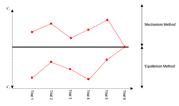
Fig 1. Comparing the mechanism method and the equilibrium method
More formally, if we find a collapse mechanism which results in the same value of from both the equilibrium method and the mechanism method, then the uniqueness theorem is satisfied and .
5.0 Plastic Analysis Method 1: Equilibrium Method
The steps to apply this method of plastic analysis are as follows:
Step 1: Identify the degree of determinacy of the structure
Step 2: Remove redundant reactions from the structure to produce a simple determinate structure
Step 3: Draw a bending moment diagram for the determinate structure under the applied loads
Step 4: Draw a bending moment diagram for the determinate structure under the redundant reactions
Step 5: Now superimpose the two moment diagrams from (3) and (4)
Step 6: Consider the superposition from (5) in such a way that a mechanism is formed
Step 7: Take equilibrium at a critical section in (6) and solve for . Check that the uniqueness theorem is satisfied.
This all sounds quite abstract at this point, so let's consider some examples.
Example 1: Encastre Beam with Asymmetric Concentrated Load
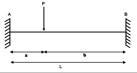
Fig 2. Example 1 general arrangement
Step 1: Identify the degree of determinacy of the structure
We have four reactions , , and and two equilibrium equations and .
Therefore, the degree of indeterminacy is .
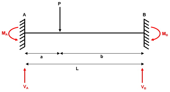
Fig 3. Example 1 reactions
Step 2: Remove redundant reactions from the structure to produce a simple determinate structure
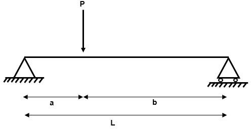
Fig 4. Example 1 determinate structure
Step 3: Draw a bending moment diagram for the determinate structure under the applied loads
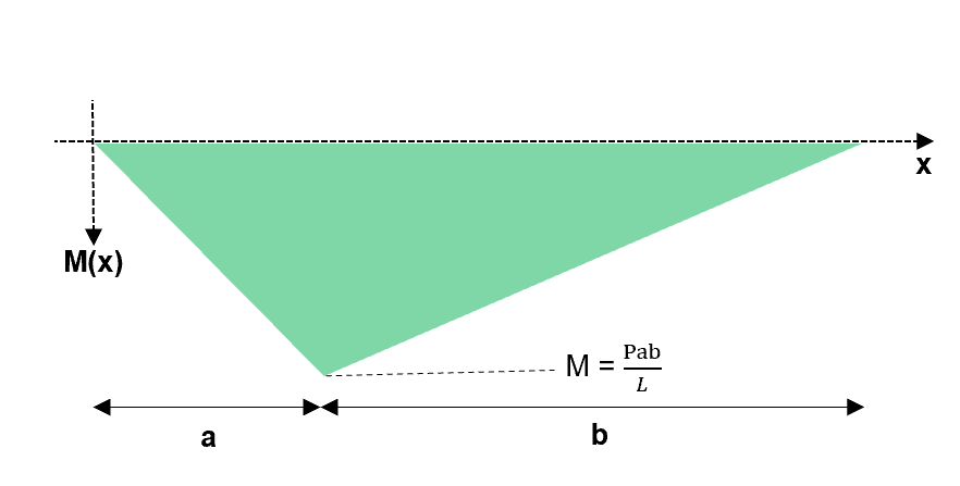
Fig 5. Bending moment diagram for the determinate structure
Step 4: Draw a bending moment diagram for the determinate structure under the redundant reactions
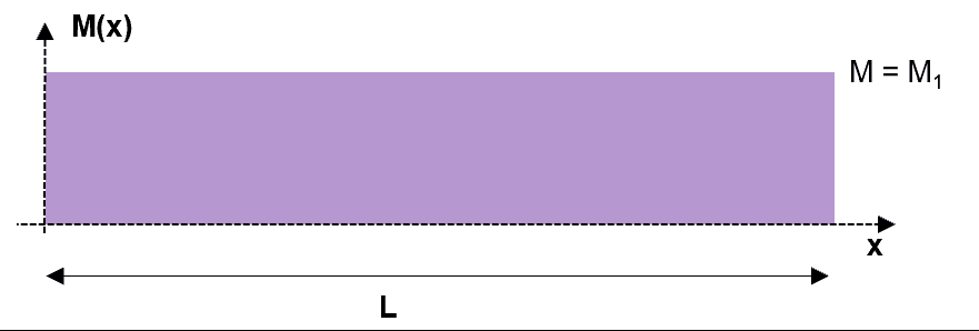
Fig 6. Bending moment diagram under the redundant reactions
Step 5: Now superimpose the two moment diagrams from (3) and (4)
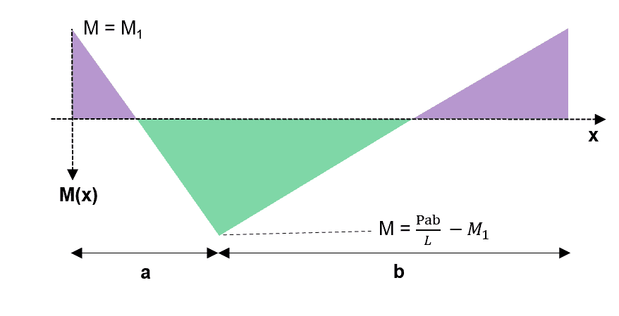
Fig 7. Superimposition of the two previous bending moment diagrams
Step 6: Consider the superposition from (5) in such a way that a mechanism is formed
So how do we do this?
We know that the structure is indeterminate to the 2nd order . A good rule of thumb to follow is that the minimum number of hinges required for collapse is .
So let us place three hinges in our structure at the locations of maximum bending moment. At hinge locations, we know that because the moment cannot exceed the plastic section capacity.
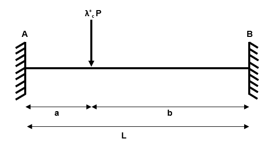
Fig 8. Increasing the applied load
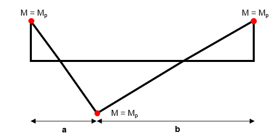
Fig 9. Considering the location of plastic hinges
Step 7: Now take equilibrium at a critical section to solve for
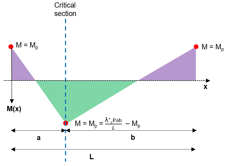
Fig 10. Taking a critical section to determine the critical load factor
Taking equilibrium at the designated section:
At this point it is good practise to reflect on the three criteria of the uniqueness theorem. If the three criteria are met then we have found the actual collapse load factor .
1. Equilibrium Condition - OK
2. Yield Condition - OK
3. Mechanism Condition - OK
This is as far as we can take this problem because we don't have defined values of , , or . If we have all of these values then is the single unknown and we can solve for it. tells us how much greater the applied load would need to be in order to cause plastic collapse via the defined mechanism.
Example 2: Two Span Continuous beam with Symmetric Concentrated Load

Fig 11. Example 2 general arrangement
Step 1: Identify the degree of determinacy of the structure
We have three reactions , and and two equilibrium equations and .
Therefore, the degree of indeterminacy is .

Fig 12. Example 2 reactions
Step 2: Remove redundant reactions from the structure to produce a simple determinate structure

Fig 13. Example 2 determinate structure
Step 3: Draw a bending moment diagram for the determinate structure under the applied loads

Fig 14. Bending moment diagram for the determinate structure
Step 4: Draw a bending moment diagram for the determinate structure under the redundant reactions

Fig 15. Redundant reactions on the beam

Fig 16. Bending moment diagram under the redundant reactions
Step 5: Now superimpose the two moment diagrams from (3) and (4)

Fig 17. Superimposition of the two previous bending moment diagrams
Step 6a/7a: Consider the superposition from (5) in such a way that a mechanism is formed
We know that the structure is indeterminate to the 1st order . Again, a good rule of thumb to follow is that the minimum number of hinges required for collapse is .
So, just like before, we place two hinges in our structure at the locations of maximum bending moment. At hinge locations, we know that because the moment cannot exceed the plastic section capacity.

Fig 18. Increasing the applied load

Fig 19. Taking a critical section to determine the critical load factor
Taking equilibrium at the designated section:
Reflecting on the three criteria of the uniqueness theorem:
1. Equilibrium Condition - OK
2. Yield Condition - OK
3. Mechanism Condition - Hmmm...will our structure collapse with the hinges in the locations we have decided? The two hinges can accept infinite rotation but because there is no central hinge, a full collapse will not occur.
In fact, the solution we have identified satisfies the lower bound theorem which means that the real collapse load factor is greater than the one we have calculated i.e. we are on the safe side.
Step 6b/7b: Consider the superposition from (5) in such a way that a mechanism is formed
However, as we have discussed, it is important that we can determine the actual collapse load factor. So let's revisit our superposition from (5).
We can't place hinges at A or C because these locations are pin supports which can't support bending moments. But what about the central support at B?
Yes, support B is also a pin support but we know that for a continuous beam we need continuity of rotation across this support. To maintain this continuity, we need a hogging bending moment at this location. Ok, so let us place an additional hinge at this location.

Fig 20. Increasing the applied load

Fig 21. Taking a critical section to determine the critical load factor
Again, taking equilibrium at the designated section:
Again, checking the three uniqueness theorem criteria
1. Equilibrium Condition - OK
2. Yield Condition - OK
3. Mechanism Condition - OK
Great, we have found the actual collapse load factor of this structure!
Example 3: Propped Cantilever with Two Concentrated Loads
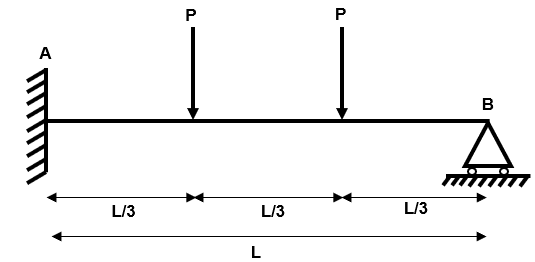
Fig 22. Example 3 general arrangement
Step 1: Identify the degree of determinacy of the structure
We have three reactions , and and two equilibrium equations and .
Therefore, the degree of indeterminacy is .
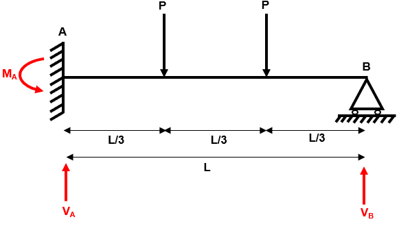
Fig 23. Example 3 reactions
Step 2: Remove redundant reactions from the structure to produce a simple determinate structure
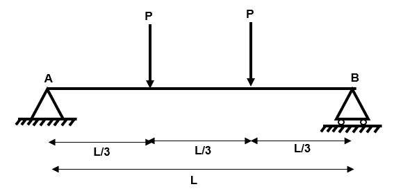
Fig 24. Example 3 determinate structure
Step 3: Draw a bending moment diagram for the determinate structure under the applied loads

Fig 25. Bending moment diagram for the determinate structure
Step 4: Draw a bending moment diagram for the determinate structure under the redundant reactions

Fig 26. Redundant reactions on the beam
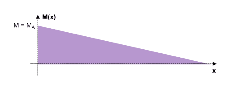
Fig 27. Bending moment diagram under the redundant reactions
Step 5: Now superimpose the two moment diagrams from (3) and (4)
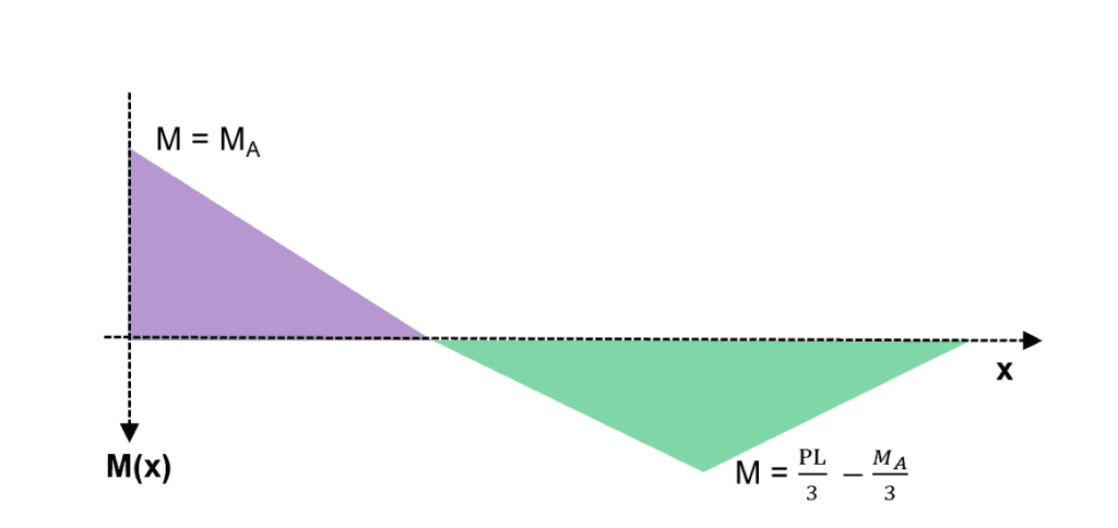
Fig 28. Superimposition of the two previous bending moment diagrams
Step 6a/7a: Consider the superposition from (5) in such a way that a mechanism is formed
As before, we increase the load P to and consider how the bending moment diagram will respond.
We know that the structure is indeterminate to the 1st order .So let us place two hinges in our structure at the locations of maximum bending moment. At hinge locations, we know that because the moment cannot exceed the plastic section capacity.
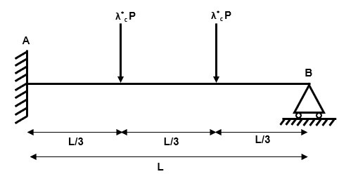
Fig 29. Increasing the applied load
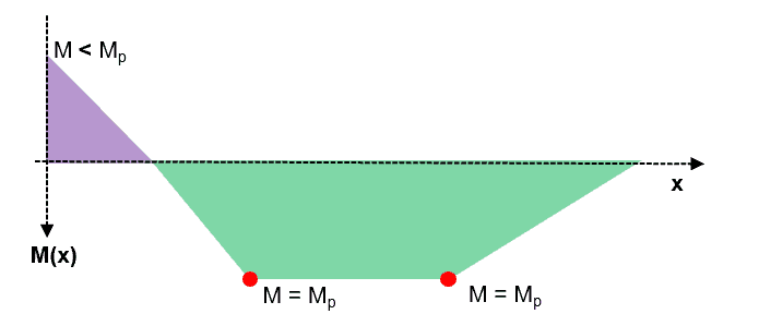
Fig 30. Possible hinge locations in the beam
1. Equilibrium Condition - NOT OK
2. Yield Condition - N/A
3. Mechanism Condition - N/A
Our proposed collapse mechanism must be in equilibrium with the applied loads. If we identify a mechanism which is not in equilibrium we immediately discount it!
Step 6b/7b: Consider the superposition from (5) in such a way that a mechanism is formed
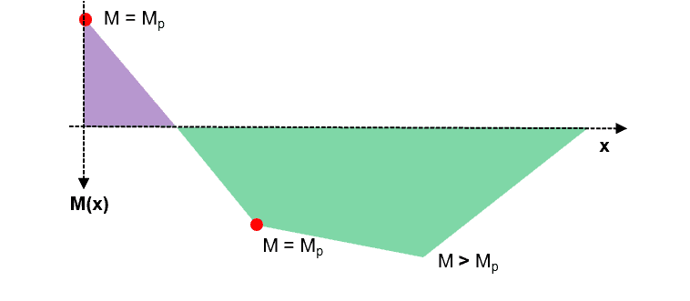
Fig 31. Possible hinge locations in the beam
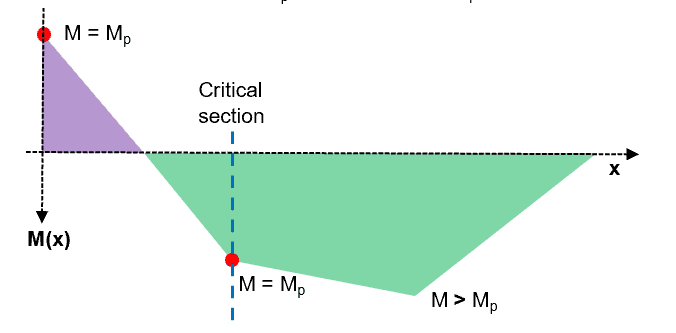
Fig 32. Taking a critical section to determine the critical load factor
1. Equilibrium Condition - OK
2. Yield Condition - NOT OK
3. Mechanism Condition - OK
Our proposed collapse mechanism does not pass the yield criteria because to be in equilibrium, there is a location where ....we know that this is not possible as the maximum moment capacity is the plastic moment moment capacity .
In fact, the solution we have identified satisfies the upper bound theorem which means that the real collapse load factor is less than the one we have calculated i.e. we are on the unsafe side.
For completeness, let us calculate so that we can compare it with the actual collapse load factor.
Taking equilibrium at the designated section:
Step 6c/7c: Consider the superposition from (5) in such a way that a mechanism is formed
Ok, so we are still searching for a collapse mechanism which meets all three of the uniqueness theorem criteria
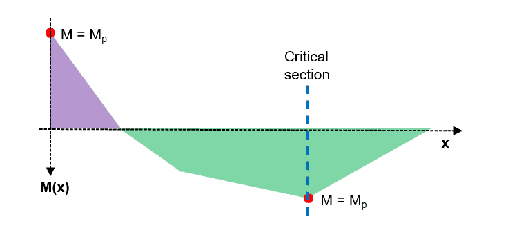
Fig 33. Taking a critical section to determine the critical load factor
Taking equilibrium at the designated section:
1. Equilibrium Condition - OK
2. Yield Condition - OK
3. Mechanism Condition - OK
Importantly,
which confirms that our earlier solution (6b/7b) was an upper bound (unsafe) solution because it over-predicted the collapse load.
Ok, so we have looked at three examples using the equilibrium method of plastic analysis. Now let us re-visit these three examples using the mechanism method. As disussed, when we identify the unique and real solution using the mechanism method, it will be equal to that obtained with the equilibrium method.
6.0 Plastic Analysis Method 2: Mechanism Method
The steps to apply this method of plastic analysis are as follows:
Step 1: Identify the degree of determinacy of the structure
Step 2: Determine all locations where plastic hinges could form
Step 3: Define and determine all independent collapse mechanisms
Step 4: Define and determine all composite collapse mechanisms
Step 5: For each collapse mechanism from (3) and (4), calculate using the virtual work method
Step 6: Select the mechanism that gives the lowest and check that
Example 1: Encastre Beam with Asymmetric Concentrated Load
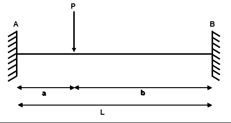
Fig 34. Example 1 general arrangement
Step 1: Identify the degree of determinacy of the structure
We have four reactions , , and and two equilibrium equations and .
Therefore, the degree of indeterminacy is .

Fig 35. Example 1 reactions
Step 2: Determine all locations where plastic hinges could form
This step will become easier with practise, as you will develop an intuition for the common failure mechanisms. However, a simple rule of thumb to follow is that plastic hinges CAN form at the following locations in a beam:
- At points where concentrated loads are applied
- At points of zero shear force (i.e. points of inflection in a bending moment diagram)
- At supports which can develop a moment i.e. fixed or continuous
But how many hinge locations should we be looking for?
Following our rule of thumb that the minimum number of hinges for collapse is where is the degree of static indeterminacy, we should be looking for a minimum of three hinge locations in this example.
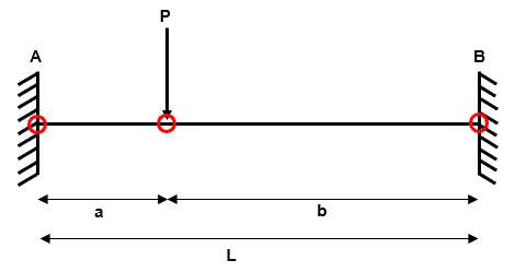
Fig 36. Identifying the possible hinge locations in the beam
Step 3: Define and determine all independent collapse mechanisms
An independent mechanism is an arrangement of plastic hinges within the system which will result in plastic collape. We have a system which has plastic hinge locations and is indeterminate to the 2nd degree .
A simple rule to follow when determining the total number of independent collapse mechanisms is that:
where is the total number of possible independent mechanisms.
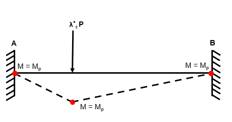
Fig 37. Independent mechanism 1
Step 4: Define and determine all composite collapse mechanisms
Composite (or combined) mechanisms manifest by combining two independent mechanisms. In certain situations (especially plastic frames), a composite mechanism will yield a smaller collapse load factor than any of the independent mechanisms (and therefore we must identify it!)
Luckily, we have a rule of thumb for determining how many combined mechanisms we should be looking for:
where is the total number of independent and composite mechanisms.
And since we know the number of independent mechanisms from (3), we can define as the number of composite mechanisms.
Step 5: For each collapse mechanism from (3) and (4), calculate using the virtual work method
We now have to inspect each independent mechanism (of which we have ) and each composite mechanism (of which we have ).
At this point we introduce the application of the virtual work method to plastic analysis.
Virtual work theory tell us that if a system of forces which is in equilibrium is subjected to a virtual displacement, then the work done by the external forces and internal forces is equal and opposite. We can say:
and from this simple statement we can say:
In this example we only have one mechanism to inspect, and we proceed as follows:
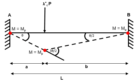
Fig 38. Using the virtual work method to identify the collapse load factor
Step 6: Select the mechanism that gives the lowest and check that
We have just one independent mechanism to consider in this example. We have obtained exactly the same solution using the mechanism method as we did with the equilibrium method (which is what we would expect!).
Finally, it is good practise to check that that we have met the criteria of the uniqueness theorem. By its nature, the mechanism method guarantees that we have met the equilibrium and mechanism condition (because we are considering the equilibrium of work done inherently and we are only checking real mechanisms)...so the final criteria to validate is the yield criteria.
By considering our mechanism, we can say that the moment nowhere exceeds and hence the yield criteria is met.
Therefore, we can say that
Note: in fact, if we find a mechanism which yields an identical solution using both the equilibrium method and the mechanism method then by inspection we have found a solution which meets the uniqueness criterion and is hence the actual collapse load.....why?....let us recall one of the earliest figures from this tutorial which graphically confirms this theory.

Fig 39. Comparing the mechanism method and the equilibrium method
Example 2: Two Span Continuous beam with Symmetric Concentrated Load

Fig 40. Example 2 general arrangement
Step 1: Identify the degree of determinacy of the structure
We have three reactions , and and two equilibrium equations and .
Therefore, the degree of indeterminacy is .

Fig 41. Example 2 reactions
Step 2: Determine all locations where plastic hinges could form
Recall that a simple rule of thumb to follow is that plastic hinges CAN form at the following locations in a beam:
- At points where concentrated loads are applied
- At points of zero shear force (i.e. points of inflection in a bending moment diagram)
- At supports which can develop a moment i.e. fixed or continuous
But how many hinge locations should we be looking for?
The minimum number of hinges for collapse is where n is the degree of static indeterminacy, we should be looking for a minimum of two hinge locations in this example.
In fact, we can identify three hinge locations in this example.

Fig 42. Identifying the possible hinge locations in the beam
Step 3: Define and determine all independent collapse mechanisms
A simple rule to follow when determining the total number of independent collapse mechanisms is that:
where is the total number of possible independent mechanisms.
Independent Mechanism 1

Fig 43. Independent mechanism 1
Independent Mechanism 2

Fig 44. Independent mechanism 2
Step 4: Define and determine all composite collapse mechanisms
We have a rule of thumb for determining how many combined mechanisms we should be looking for:
Composite Mechanism 1

Fig 45. Composite mechanism 1
Step 5: For each collapse mechanism from (3) and (4), calculate using the virtual work method
Independent Mechanism 1

Fig 46. Using the virtual work method to identify the collapse load factor
Independent Mechanism 2

Fig 47. Using the virtual work method to identify the collapse load factor
Composite Mechanism 1

Fig 48. Using the virtual work method to identify the collapse load factor
Step 6: Select the mechanism that gives the lowest and check that
Ok, so we have identified three different mechanisms in this example (two independent and one composite).
In this example, all three mechanisms yield the same .
Again, we have reached an identical solution to the one obtained using the equilibrium method. Not only does this prove that the two methods can be used interchangeably, but it also tells us that we have met the criteria for the uniqueness theorem and hence:
Example 3: Propped Cantilever with Two Concentrated Loads

Fig 49. Example 3 general arrangement
Step 1: Identify the degree of determinacy of the structure
We have three reactions , and and two equilibrium equations and .
Therefore, the degree of indeterminacy is .

Fig 50. Example 3 reactions
Step 2: Determine all locations where plastic hinges could form
Recall that a simple rule of thumb to follow is that plastic hinges CAN form at the following locations in a beam:
- At points where concentrated loads are applied
- At points of zero shear force (i.e. points of inflection in a bending moment diagram)
- At supports which can develop a moment i.e. fixed or continuous
But how many hinge locations should we be looking for?
The minimum number of hinges for collapse is where n is the degree of static indeterminacy, we should be looking for a minimum of two hinge locations in this example.
In fact, we can identify three hinge locations in this example.
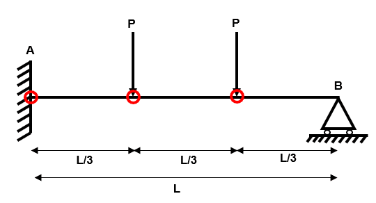
Fig 51. Identifying the possible hinge locations in the beam
Step 3: Define and determine all independent collapse mechanisms
A simple rule to follow when determining the total number of independent collapse mechanisms is that:
where is the total number of possible independent mechanisms.
Independent Mechanism 1
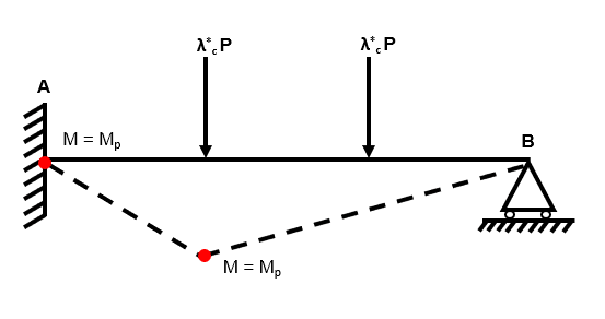
Fig 52. Independent mechanism 1
Independent Mechanism 2
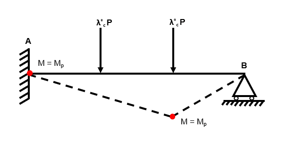
Fig 53. Independent mechanism 2
Step 4: Define and determine all composite collapse mechanisms
We have a rule of thumb for determining how many combined mechanisms we should be looking for:
Composite Mechanism 1
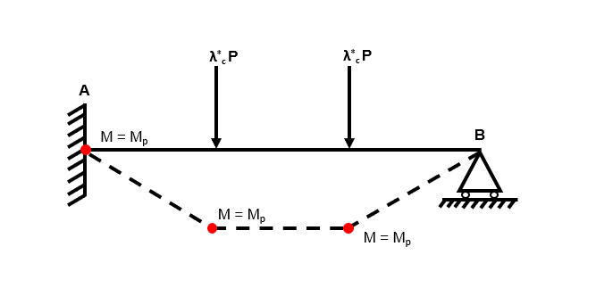
Fig 54. Composite mechanism 1
Step 5: For each collapse mechanism from (3) and (4), calculate using the virtual work method
Independent Mechanism 1
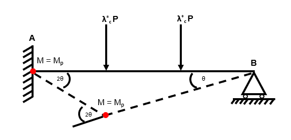
Fig 55. Using the virtual work method to identify the collapse load factor
Independent Mechanism 2
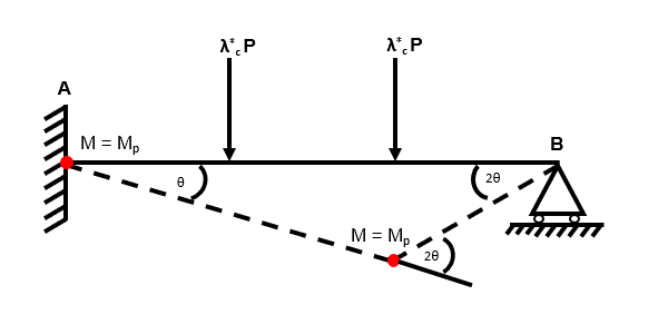
Fig 56. Using the virtual work method to identify the collapse load factor
Composite Mechanism 1
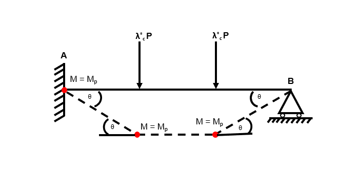
Fig 57. Using the virtual work method to identify the collapse load factor
Step 6: Select the mechanism that gives the lowest and check that
So we can see that independent mechanism 1 yields the smallest value of . Again, this result matches our result from the application of the equilibrium method to the same example. This tells us that we have satisfied the three criteria of the uniqueness theorem and therefore = = .
For completeness, let us think about the other two proposed mechanisms.
Independent mechanism 2 yields = . As we discussed, a collapse mechanism which results in a tells us that the uniqueness theorem is not satisfied. Instead, we have identified an upper bound solution, which itself tells us that the yield criteria of the uniqueness theorem cannot be satisfied....which we showed in the application of the equilibrium method.
Unlike within the equilibrium method, we have identified a collapse mechanism using the mechanism method which requires three hinges, this is our composite mechanism 1. Compsite mechanism 1 resulted in = which again indicates that this is an upper bound solution which must have failed to meet the yield criteria.
12.0 Wrapping up
Within part 1 of this tutorial series, we have discussed:
- the importance of plastic analysis,
- the fundamental prerequisite properties a structural system must exhibit to permit us to conduct plastic analysis
- and two alternative methods for calculating the plastic collapse load of beams.
We applied these two alternative methods to three different examples and this allowed us to investigate how we use the theory to ensure that we have determined the true (and minimum) collapse load factor .
In reality, plastic analysis is often used on more complicated structural systems, such as frames. However, it is necessary to understand the fundamental principles of plastic analysis before proceeding to more complex structures.
In part 2, we will build upon our new understanding and explore more advanced examples of plastic analysis.
I hope you have found the content useful and informative – if you did, tell someone else who might also find it helpful!
Featured Tutorials and Guides
If you found this tutorial helpful, you might enjoy some of these other tutorials.
Column Buckling and Stability
Long slender structural elements in compression will typically fail due to buckling rather than direct compression. In this post we'll explore column buckling

Dr Seán Carroll


