Plate Girder Design to Eurocode 3
![[object Object]](/_next/image?url=%2Fimages%2Fauthors%2Fcallum_wilson.jpg&w=256&q=75)

Welcome to the fourth tutorial in this steel design series. This one is focused on plate girder design to Eurocode 3. The previous three tutorials…
- Steel Beam Design - A Step-by-Step Guide using Eurocode 3
- Steel Column Design using Eurocode 3 - A Complete Guide
- Steel Truss Design to Eurocode 3
…have all focused exclusively on Eurocode 3 Part 1-1 General Rules and Rules for Buildings. Whilst we will still be using Part 1-1 in this tutorial, we will also be delving into Eurocode 3 Part 1-5 - Plated structural elements.
This is another in-depth tutorial in which we’ll cover both the underlying theory and a practical design example. The tutorial is divided into the following sections:
✅ Section 1: What is a plate girder?
In section 1, we’ll introduce the plate girder and discuss how it differs from a typical hot rolled I-section. We’ll also discuss why you might want or need to design a plate girder. We’ll finish by introducing one of the main design challenges associated with plate girders - shear buckling of the web.
✅ Section 2: Shear buckling of plate girders
In this section, we dive a little deeper into shear buckling and the role of web stiffeners in increasing the shear buckling capacity of the plate girder web. We’ll also outline the Eurocode 3 calculation process for the elastic critical shear buckling stress, .
✅ Section 3: Plate girder design workflow
In section 3, we review the different design steps required to complete a code-compliant plate girder design. We’ll use the What, Where, Why and How framework to give you a good overview of the design process and the reasoning behind each step.
✅ Section 4: Lateral torsional buckling
Lateral torsional buckling or LTB is a concern for any long flexural member with inadequate top-flange restraint. This means that without careful consideration, plate girders are prone to LTB. We discuss this susceptibility in section 4.
✅ Section 5: Plate girder design example
In section 5, we’ll tie everything together with a design case study. This will allow us to put the workflow discussed in section 3 into practice. As with any new design workflow - it only really makes sense and becomes crystal clear through an example.
✅ Section 6: Initial sizing of plate girders
In the final section of the tutorial, we’ll briefly go over some common rules of thumb to help you get a quick estimate of the key plate girder dimensions, without going through a full detailed design.

1.0 What is a plate girder?
In general, the design resistance of steel beams can be increased by making the section deeper, i.e. increasing section depth . We know that increasing the depth of the section increases the lever arm to the parts of the section which do most of the hard work during bending - the flanges! Put another way, by increasing the section depth, we increase the member's moment of inertia. An increased moment of inertia increases the bending resistance and decreases the deflection.
If you have any experience designing steel beams, you will be familiar with the manufacturing method known as ’hot rolling’. Hot rolled steel members, of which the ubiquitous I-section is an example, are formed monolithically during the casting process. The web and flanges of the I-section are formed from a single piece of steel which is rolled (at extremely high temperatures) to form the I-shaped profile. Hot rolling of steel is economical when there is a high demand for the particular section geometry.
Most countries adopt a typical range of standard beam sizes which are produced using the hot rolling method. The I-section sizes within this range represent those which are most commonly used within each country. In the UK, the range is known as the 'Universal Beam (UB)' whereas in the US the range is known as the 'American Wide Flange Beam (W)'.
Taking the UK as an example, the deepest UB section that can be procured from a hot rolling manufacturer is the 1016 x 305 x 584. This I-section has a total depth of 1056mm. For many engineering applications, an I-section of this size will be more than sufficient. However, there are situations discussed below when a greater section depth is required - this leads us into the territory of plate girders.
Put simply, a plate girder is an I-section formed by welding three separate parts together - the top flange, the bottom flange and the web. Plate girders are not produced using the hot rolled method simply because the requirement for sections of this depth is rare.
1.1 Typical applications for plate girders?
Plate girders are used in engineering applications where standard size I-sections are not capable of developing the required design resistance or serviceability performance. Common applications for plate girders are as follows:
-
Medium to long-span steel road bridges
-
Rail bridges
-
Transfer structures in steel frame buildings
-
Outriggers in ultra-tall steel frame buildings
-
Oil and gas platform construction
In general, if you are trying to support large loads, particularly point loads, over large spans, then it is likely you will end up considering a plate girder.
1.2 Plate girder design challenges
At this point, you may be thinking that the plate girder is the solution to all of our engineering challenges! We can make our plate girder section deeper and deeper which will provide us a higher and higher moment of inertia, which will result in higher and higher design resistances...but are we missing something?
Well, yes we are! The major challenge when designing a plate girder is to ensure that the web of the plate girder does not buckle - more generally we refer to this as shear buckling!
Shear buckling is not unique to plate girders. In fact in the first tutorial in this series, Steel Beam Design - A Step-by-Step Guide using Eurocode 3, we checked if the web was susceptible to shear buckling.
As a refresher, EN 1993-1-1: 2005 Clause 6.2.6 (6) tells us that shear buckling for web elements must be checked if:
So from this, we can see that shear buckling will become a critical design check for large values of . You might be asking why don't we just increase the thickness of the web accordingly to maintain a ratio which is . The reason we don't do this comes down to self-weight and efficiency.
Tackling shear buckling purely by increasing web thickness is a losing battle. So, instead, we tackle the phenomenon of shear buckling head on and perform a series of Eurocode 3 design verifications which check the plate girder for its resistance to this type of failure.
Before we get into the nitty gritty of Eurocode 3 design checks, we are going to spend the next section looking at the phenomenon of shear buckling in a little more detail.
2.0 Shear buckling of plate girders
A plate subjected to pure shear stresses buckles when a critical level of shear stress is encountered. The stress at which this buckling occurs is termed the elastic critical buckling stress. It is not surprising that the elastic critical buckling stress is controlled largely by the aspect ratio of the plate - the ratio of the plate's length to its breadth.
For an unstiffened web in an I-section, shear buckling will form, as indicated in Fig 1. The underlying mechanics that describe shear buckling are interesting to explore but outside the scope of this design tutorial. The interested reader is directed towards tension field theory to learn more.
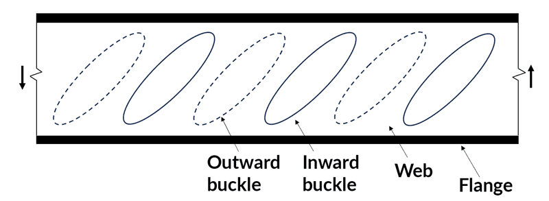
Fig 1. Web shear buckling pattern in an unstiffened web.
The inclusion of vertical (known as transverse) stiffener plates breaks up the web into a series of panels. This alters the web's aspect ratio—now a series of panels with their own aspect ratios. It is not surprising that this can significantly alter the web's buckling behaviour, as indicated in Fig 2.
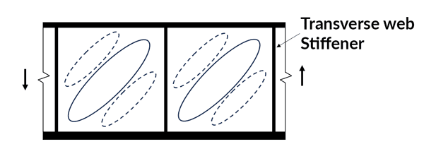
Fig 2. Web shear buckling pattern in a stiffened web.
Eurocode 3 Part 1-5 deals with shear buckling through a definition of the elastic critical shear buckling stress . This parameter is used to define a web slenderness which in turn is used to define a buckling factor . This buckling factor reduced the design resistance of the web to account for shear buckling.
The following case study assumes that you have access to a copy of Eurocode 3. We'll reference various clauses - these, unless otherwise stated, refer to Eurocode 3. Unfortunately, it's not possible to reproduce the various extracts from Eurocode 3 within this tutorial.
If you need to purchase a copy of Eurocode 3, you can do so from the British Standards Institute (BSI). A good alternative to purchasing the complete Eurocode is to purchase Structural Eurocodes: Extracts from the Structural Eurocodes for Students of Structural Design which contains the relevant sections of Eurocode 3 as well as other Eurocodes.
Structural Eurocodes: Extracts from the Structural Eurocodes for Students of Structural Design published by the British Standards Institute.
Now, let’s take a look at how is calculated. We will be using these equations in the worked example towards the end of this tutorial.
Definition of
where is the shear buckling coefficient and is the critical buckling stress for a plate under in-plane axial compression.
EN 1993-1-5: 2005 Clause 5.3 Expression 5.4
Calculation of
where,
- is the elastic modulus of steel
- is the thickness of the web
- is the height of the web
- is the Poisson's ratio of steel
EN 1993-1-5: 2005 Annex A.1
Calculation of
For the purpose of this tutorial, we will only be considering transverse stiffeners - these are found on the majority of plate girders.
For
For
where:
- is the distance between transverse stiffeners
- is the clear height of the web
- is the shear buckling coefficient for longitudinal stiffeners (which we won't have in the worked example)
EN 1993-1-5: 2005 Annex A.3
3.0 Plate girder design workflow
We’ll work through the plate girder design process using the What, Where, Why and How framework - a familiar structure if you’ve read parts 1 to 3 in this series. This will give you a good overview of the design process and the reasoning behind each step.
Step 1: Determine the yield strength of steel
What?
In step 1, we need to assign a value of yield strength, , to our steel member elements, i.e. the flanges and the web.
Where?
EN 1993-1-1: 2005 Table 3.1
Why?
The yield strength of steel is a description of the limit of elastic behaviour for the material. Yield strength is the predominant material property used in steel design for Eurocode 3.
How?
-
From your project specification, find the specified steel grade. This will typically be S275 or S355.
-
From the section geometry drawing, find the maximum steel thickness. This will typically be the flange thickness for a plate girder.
-
Using Table 3.1, identify
Step 2: Classify the cross-section
What?
In step 2, we need to classify the geometry of the member cross-section. In Eurocode 3, four classifications are defined. The classification is based on the ability of a member to develop its full plastic section capacity.
-
Class 1 cross-sections are those which can form a plastic hinge with the rotation capacity required from plastic analysis without reduction of the resistance.
-
Class 2 cross-sections are those which can develop their plastic moment resistance, but have limited rotation capacity because of local buckling.
-
Class 3 cross-sections are those in which the stress in the extreme compression fibre of the steel member assuming an elastic distribution of stresses can reach the yield strength, but local buckling is liable to prevent development of the plastic moment resistance.
-
Class 4 cross-sections are those in which local buckling will occur before the attainment of yield stress in one or more parts of the cross-section.
Where?
-
For the definition of the classes: EN 1993-1-1: 2005 Clause 5.5.2
-
For classification of internal compression parts: EN 1993-1-1: 2005 Table 5.2 (sheet 1 of 3)
-
For classification of outstand flanges: EN 1993-1-1: 2005 Table 5.2 (sheet 2 of 3)
Why?
Classifying our cross-section allows us to focus only on the necessary design checks for the member under consideration.
As per the definitions above, cross-sections of class 3 and class 4 are susceptible to local buckling failure prior to yielding, whereas cross-sections of class 1 and class 2 are most likely to fail due to the lack of cross-section resistance, as opposed to local buckling.
The simple cross-section classification step allows us to predict the behaviour, and hence the relevant design checks, for a member based on the thickness of its constituent parts alone.
How?
-
Using the diagrams at the top of Table 5.2 (sheet 1 of 3), identify the internal compression parts. For an I-section, this will be the web of the member.
-
Calculate the value of , making sure to account for the thickness of surrounding elements and the root radius of any joints.
-
From the section geometry drawing, determine the thickness of the internal compression part(s). Again, this is for a plate girder.
-
Calculate for the web.
-
Determine the value of by evaluating where is the yield strength determined in step 1.
-
We are considering a 'part' in pure bending and hence we need to use the left-most column of Table 5.2 (sheet 1 of 3).
-
Now classify the internal compression part of the section by checking if is less than 72 (Class 1), 83 (Class 2) or 124 (Class 3).
-
Repeat the process for the outstand flanges of the section. For a symmetrical plate girder there is just one part to check - the flange.
-
Once you have classified both the internal compression parts (the web) and the outstand flanges (the compression flange) then we are ready to classify the overall section.
-
The overall classification of the section is the lowest of the classifications of the individual parts. For example, if the internal compression part classification is class 3 and the outstand flange classification is class 1, then the section is class 3.
-
If the cross-section parts do not meet the criteria for class 3 then they are class 4.
Step 3: Full section bending resistance
What?
In step 3, we determine the cross-section's bending resistance. Eurocode 3 provides different design formulae for members' bending resistance depending on their cross-section classification (see step 2).
In general, the following should be satisfied:
where is the design bending moment acting on the member and is the member's design bending resistance.
Where?
EN 1993-1-1: 2005 Clause 6.2.5 (Exp. 6.12)
Why?
We are designing a plate girder (a type of beam) which, as stated, carries load by developing bending and shear stresses. In the first instance, we need to check that the design bending resistance is larger than the design bending moment.
How?
According to the cross-section classification from step 2, apply the relevant design formula to determine . For class 1 or 2 cross-sections, use the plastic section modulus, for class 3 cross-sections, use the elastic section modulus and for class 4 cross-sections, use the effective elastic section modulus.
For a plate girder section, you will not be able to find the section modulus (plastic, elastic or effective) in steel design tables so these properties will need to be calculated from first principles. If you need a refresher on calculating the geometric properties of sections, take a look at our tutorial, Calculating and Interpreting the Second Moment of Area.
Step 4: Flange bending resistance
What?
In step 4, we determine the bending resistance of the flanges alone.
where and are the width and depth of the flange respectively, is the height of the web and is the yield strength of the flange material.
Where?
EN 1993-1-5: 2006 Clause 7.1(3)
Why?
If we can demonstrate that the flanges alone have sufficient bending resistance, then it will not be necessary to conduct a bending and shear interaction check. If the flanges cannot provide the full bending resistance, then the web will also need to contribute to providing bending resistance; which has an impact on the shear capacity of the web.
How?
Using the above formula, calculate and compare this to the design moment.
If < , then we may need to check bending moment and shear interaction - more on this later!
Step 5: Shear resistance
What?
Now we determine the shear resistance of the cross-section. This is a simple check which uses the section’s shear area, to calculate the shear resistance. In general, the following should be satisfied:
where is the design shear force acting on the section and is the design cross-sectional shear resistance.
Where?
EN 1993-1-1: 2005 Clause 6.2.6
Why?
We have considered the bending resistance of the section in step 3 and now we need to consider the shear resistance. It is worth noting that for plate girder sections, which have very deep webs, this check is typically not critical. The governing shear check is that of shear buckling - which comes next!
How?
-
Calculate the shear area for the section in question using the expressions in 6.2.6 (3).
-
Confirm from your structural analysis that the member is not subject to torsion.
-
If 2) is validated then proceed to calculate the plastic shear resistance using formula (6.18).
-
is the partial factor for resistance of cross-sections regardless of the section class. The value can be found in 6.1 Note 2B.
Step 6: Shear buckling susceptibility
What?
Up to this point, we have been conducting checks based on the cross-section resistance of the member. In step 5, we take a slight change of direction and conduct a check which assesses the buckling resistance of the web of the member. This is typically the critical design check for plate girders.
Where?
EN 1993-1-1: 2005 Clause 6.2.6 Expression (6.22)
Why?
Plate girders are deep sections with tall webs. Therefore most plate girder sections will be susceptible to shear buckling - this is one thing that sets them apart from regular hot-rolled beam sections in terms of design.
Eurocode 3 tells us 'the shear buckling resistance for webs without intermediate stiffeners should be according to section 5 of EN 1993-1-5, if:'
How?
This is a simple check to make.
-
Calculate which is the clear height of the web i.e. the total section height minus the flange thicknesses minus the root radii.
-
From your section geometry drawing, identify the web thickness .
-
Take the value of from step 2.
-
Use the recommended value of
-
Evaluate the inequality and check if the section is susceptible to shear buckling.
Step 7: Shear buckling resistance
What?
As already discussed, plate girders typically have deep webs and this makes them susceptible to shear buckling. Once the design check in step 6 has identified a web which is susceptible to shear buckling, we jump to EN1993-1-5 to calculate the shear buckling resistance of the web.
Where?
EN 1993-1-5:2006 Clause 5.1(2)
Why?
When we design a standard I-section beam, we aren't typically worried about shear buckling. When assessing shear resistance for these standard sections, the shear resistance is simply the product of the shear area and the design yield strength of the steel. However, for plate girders, which typically have slender webs, shear buckling will occur at a value of shear force which is much less than the plastic shear resistance of the section. It is therefore important to capture the reduced capacity of the web under shear.
How?
-
Using EN 1993-1-5:2006 Clause 5.1(2), confirm that the web needs to be checked for shear buckling. Note that the criteria is different for stiffened and unstiffened webs.
-
EN 1993-1-5:2006 Clause 5.2 Expression 5.1 states the following:
- We first make the simplification that i.e. that the flanges do not contribute to the shear resistance for the section. One might classify this approach as basic tension field action.
-
Calculate using EN 1993-1-5:2006 Annex A.3 and section 4.0 of this tutorial.
-
Calculate using EN 1993-1-5:2006 Clause 5.3 Expression 5.4
-
Calculate using EN 1993-1-5:2005 Clause 5.3 Expression 5.3
-
Using the value of , obtain from EN 1993-1-5:2005 Table 5.1
-
Now revisit 3 above and calculate
-
Check if . If so, then the web alone has sufficient capacity to resist the entire design shear force. If not, then must be calculated and the flanges must assist the web in resisting the shear forces.
-
EN 1993-1-5:2006 Clause 5.4(1) tells us that 'When the flange resistance is not completely utilised in resisting the bending moment () the contribution from the flanges should be obtained as follows'.
If we look at this expression, it is clear how the shear resistance of the flange is accounted for. In regions of high bending moment, i.e close to the value of , the flange cannot 'spare' much capacity to assist with resisting shear. In regions of lower bending moment, the flange has excess resistance and can, therefore, assist with resisting shear.
Now, think back to your very first bending moment diagram of a simply supported beam subject to UDL. Where is the highest shear force? At the support! Where is the highest bending moment? At mid-span!
So, we very rarely have a case where we have simultaneously high bending moments and shear forces which allows our plate girder flanges to provide resistance to the critical internal force at each location along the beam.
Step 8: Moment and shear interaction
What?
This design check is necessary to determine whether the presence of high shear forces reduces the bending moment resistance of the plate girder section. You might recall a similar check which is conducted for standard I-beam sections.
Where?
EN 1993-1-5: 2006 Clause 7.1
Why?
It must be demonstrated that the plate girder can resist the combined effects of bending moment and shear force.
How?
- Using EN 1993-1-5:2006 Clause 5.5 (1) Expression 5.10, calculate
-
If then the design bending resistance does not need to be reduced to allow for the shear forces.
-
If , then the combined effects of bending and shear should satisfy the following
for
where
Step 9: Serviceability check
What?
So far, all of the design checks we have completed have been ultimate limit state (ULS) checks. We must not overlook the serviceability limit state (SLS) design checks as these can often govern member design in practice. For example, a steel beam spanning between two columns may well have sufficient capacity at ULS but it may deflect to the extent that it does not function in service.
Where?
EN 1990 – Annex A1.4
Why?
We complete these design checks to ensure that the steel member functions when under service conditions.
How?
We need to determine the maximum deflection in the plate girder. Typically we are considering deflection in the vertical axis but there are situations when horizontal deflection is relevant.
For statically determinate beams with simple loading arrangements, closed-form expressions for the deflection can be read from tables. For the more realistic statically indeterminate beams and for beams with complex loading arrangements, a software package or code-based solution is usually the quickest way to obtain deflections. Remember that for a plate girder section, you will need to calculate the second moment of area for the section.
All that remains is to compare the observed deflection against a deflection limit, which will often be set by individual project requirements.
4.0 Lateral torsional buckling
If you have completed the EngineeringSkills beam design tutorial, then you will be familiar with the design checks we conducted to assess the design resistance of a beam against lateral torsional buckling (LTB). So you might ask yourself why we haven't conducted LTB design checks for our plate girder?
You are absolutely right to question this! A plate girder can be susceptible to LTB in the same way as any other ‘standard’ beam. In fact, very deep plate girders are particularly susceptible to LTB since they are often used over long spans and are inherently slender due to their deep profiles.
Now, we could assess the plate girder using the workflow outlined in our previous beam design tutorial. We could calculate and reduce the bending resistance of our plate girder accordingly. However, we would quickly find the value to be very small, and consequently, the bending resistance for the plate girder would be extremely low.
In practise, however, plate girders are normally designed on the assumption that they will have a high degree of top flange restraint. During erection, this restraint is often provided by permanent or temporary cross-bracing between pairs of plate girders. When plate girders are restrained against each other, the calculation of non-dimensional slenderness and LTB reduction factor must account for the behaviour of the braced pair of girders. This type of assessment is outside the scope of this article.
During construction, a concrete topping will typically be poured over the top flange of plate girders. Once this concrete flange has reached strength, it provides full restraint to the top flange of the plate girder and hence prevents LTB from occurring during service.
So, to conclude, we will not be considering LTB of the plate girder during the worked example that follows because it is usually designed out through the general arrangement of the structure.
5.0 Plate girder design example
5.1 Setting up the problem
In this example we are going to look at the analysis and design of a simply supported plate girder subject to a uniformly distributed load (UDL). As discussed above, plate girders are typically used for particularly long spans or particularly heavy loading. For this example, we are going to look at a plate girder with a modest span but a total design load (ULS) of .
The plate girder is going to be fabricated from a web and two flanges. All steel within the plate girder has a yield strength of .
Adequate transverse stiffeners are provided at centres along the plate girder and the end posts are classified as non-rigid.
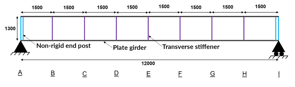
Fig 3. Plate girder design example general arrangement.
5.2 Structural analysis
Now we progress to the analysis stage which will allow us to determine the internal forces (against which we will conduct our member design checks). For a simply supported beam subject to a UDL, a simple hand-calculation will be sufficient to calculate the bending moments and shear forces.
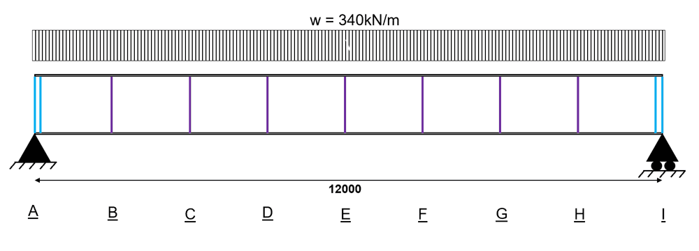
Fig 4. Plate girder design example loading.
We need to extract the internal bending moment and shear force at points A to I. We do this because we might need to check the interaction of bending moment and shear force at these locations.
This interaction will vary along the length of the beam, since the bending moment and shear force also vary along the length. The reason we have identified points A to I is that they align with the beam supports and with the transverse stiffeners. When looking at plate girder design, we call the region between stiffeners a 'panel', Fig 5.
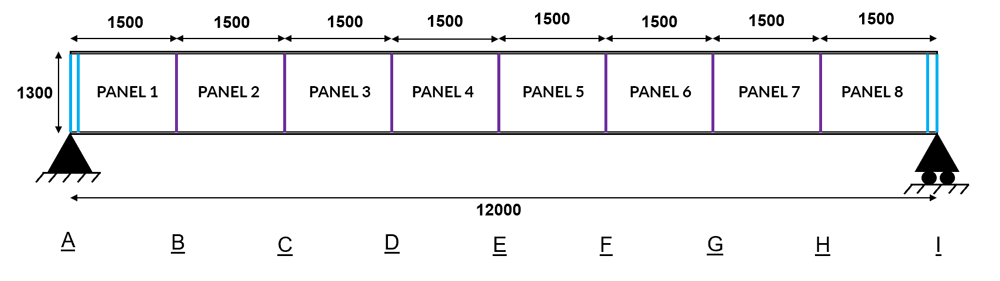
Fig 5. Discretisation of the plate girder into panels.
5.2.1 Bending moments
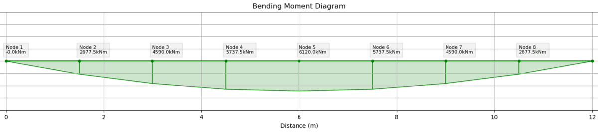
Fig 6. Bending moment diagram.
5.2.2 Shear forces
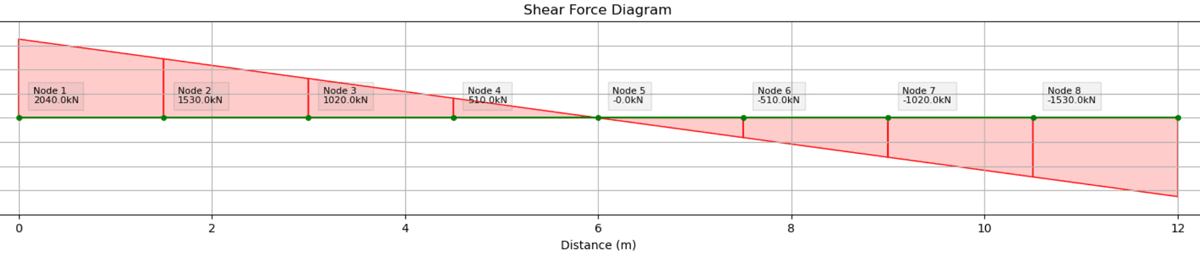
Fig 7. Shear force diagram.
5.2.3 Summary of internal forces
For convenience, we combine the shear force and bending moment at each point into a table. These are the shear and moment combinations against which each panel must be checked. With the structural analysis complete, we can move forward with the design.
| Panel | [] | [] |
|---|---|---|
| A | 0 | 2040.0 |
| B | 2677.5 | 1530.0 |
| C | 4590.0 | 1020.0 |
| D | 5737.5 | 510.0 |
| E | 6120.0 | 0 |
| F | 5737.5 | 510.0 |
| G | 4590.0 | 1020.0 |
| H | 2677.5 | 1530.0 |
| I | 0 | 2040.0 |
5.3 Cross-section classification
Step 1: Determine the yield strength of the steel,
- Our section is S275 steel
- We have
N/mm
EN 1993-1-1: 2005 Table 3.1
Step 2a: Classify the cross-section - Outstand of compression flange (welded section)
The limiting value for a Class 1 section is .
Evaluating the limiting value:
the flange in compression is Class 1
EN 1993-1-1: 2005 Table 5.2 (sheet 2 of 3)
Step 2b: Classify the cross-section - Web
The limiting value for a Class 3 section is .
Evaluating the limiting value:
the section of web in compression is Class 3
EN 1993-1-1: 2005 Table 5.2 (sheet 1 of 3)
Step 2c: Overall classification
The flange is Class 1. The web is Class 3. Therefore, the overall section classification is Class 3.
5.4 ULS Checks
5.4.1 Full-section bending resistance
Step 3: Overall Bending resistance
At this point in the design, we are following the same method as we would for a normal beam section i.e. using Eurocode 3 Part 1-1. We do this because our section classification is class 3. Had the section classification been class 4 then we would have needed to jump directly into Eurocode 3 Part 1-5.
We know that according to Eurocode 3 Part 1-1,
EN 1993-1-1: 2005 Clause 6.2.5 (Exp. 6.12)
We have a Class 3 section, and therefore, the following applies:
EN 1993-1-1: 2005 Clause 6.2.5 (Exp. 6.14)
the bending moment resistance of the entire section (without considering interaction) is adequate.
5.4.2 Flange-only bending resistance
This check for flange-only bending resistance is found within Eurocode 3 Part 1-5 and is necessary to allow us to determine whether or not a bending and shear interaction check will be necessary.
Step 4: Flange Only Bending resistance
EN 1993-1-5: 2005 Clause 7.1(3)
Therefore, the bending moment resistance of the flanges alone is insufficient to resist the full design bending moment. This means that the web is required to assist in providing bending resistance. This also means that a shear and bending interaction check may be necessary (more on this later).
5.4.3 Shear resistance
Once again, this is a design check from Eurocode 3 Part 1-1. As we discussed earlier, the plastic shear resistance of the web in plate girders is rarely critical since it is the shear buckling case which typically governs. Notwithstanding, it is good practice to demonstrate the plastic resistance of the section.
Step 5: Shear resistance
We need to validate the following expression for the axis:
EN 1993-1-1: 2005 Clause 6.2.6 (Exp. 6.17)
where is the shear area
EN 1993-1-1: 2005 Clause 6.2.6 (Exp. 6.18)
We are considering a welded I section and, therefore, for load parallel to the web (i.e. along the -axis):
EN 1993-1-1: 2005 Clause 6.2.6 (3)
Therefore, the shear force resistance of the proposed section is adequate. Note that this design check does not consider the potential for shear buckling behaviour (see below).
5.4.4 Shear buckling resistance
A key element of plate girder design is to understand the potential for web shear buckling. This is often the critical design check for I-section plate girders.
EN 1993-1-1: 2005 Clause 6.2.6 (6)** tells us the following.
'In addition, the shear buckling resistance for webs without intermediate stiffeners should be according to section 5 of EN1993-1-5, if'
Whilst we know that our chosen plate girder section does have intermediate stiffeners, we use this design check as our indicator to move across to EN1993-1-5.
Therefore we move to EN1993-1-5 to assess shear buckling resistance.
Step 6: Shear buckling susceptibility
EN 1993-1-5: 2006 Clause 5.1 (2)** tells us the following.
_'Plates with greater than for an unstiffened web, or for a stiffened web, should be checked for resistance to shear buckling and should be provided with transverse stiffeners at the supports...'_
Our proposed plate girder section has transverse stiffeners at centres and hence we need to validate the following.
We have all of the values in this expression except for . So, let us work this out.
EN 1993-1-5: 2006 Clause Annex A.3 (Expression A.5)
So, we need to check the stiffened web for resistance to shear buckling.
Step 7a: Shear buckling resistance (web contribution)
The design shear resistance of stiffened webs is given by EN 1993-1-5:2005 Clause 5.2 Expression 5.1:
We start by considering the contribution from the web which is given by EN 1993-1-5:2005 Clause 5.2 Expression 5.2:
There are a few steps for us to follow before we can calculate . So, let’s go through them one by one.
Calculate using EN 1993-1-5:2005 Annex A.3
EN 1993-1-5: 2006 Clause Annex A.3 (Expression A.5)
Calculate using EN 1993-1-5:2005 Clause 5.3 Expression 5.4
EN 1993-1-5: 2006 Clause Annex A.1 (Expression A.1)
EN 1993-1-5: 2006 Clause 5.3 (Expression 5.4)
Calculate using EN 1993-1-5:2005 Clause 5.3 Expression 5.3
Using the value of , obtain from *EN 1993-1-5:2005 Table 5.1. We have a case of non-rigid end posts and hence we use the right-hand column of Table 5.1.
We have and therefore:
Now, we can revisit the original expression for .
Evaluating the utility factor,
Therefore, the shear buckling resistance of the web alone is not adequate. This means that we need to consider the contribution of the flanges to resist shear.
Step 7b: Shear buckling resistance (flange contribution)
We have demonstrated that the shear buckling resistance of the web alone is insufficient to resist the maximum design shear force. We, therefore, need to consider the contribution that the flanges make to the overall shear resistance.
EN 1993-1-5:2005 Clause 5.4(1)
where
is not larger than 15 on each side of the web
and
Evidently, the magnitude of depends on the value of at the chosen location. The Engineer must consider the variation of bending moment and shear force and conduct the check at each location where . In our case, we have just two locations (A and I). At both these locations, .
and,
So, the combined shear resistance of the web and the flanges is adequate at the location where . In essence, we have shown that when the flanges are not involved in resisting bending moments, they are beneficial to the shear buckling resistance of the section.
5.4.5 Moment and shear interaction resistance
For the nine critical points throughout the section, we are going to determine if a bending and shear interaction check is required. We’ll track this in a simple table.
Step 8: Bending moment and shear interaction
EN 1993-1-5:2005 Clause 7.1 tells us that a bending and shear interaction check only needs to be conducted if the following two conditions are both met for a given section:
- , where;
AND
- , where;
So, in the following table we simply check these two criteria at each of the nine sections along the beam.
| Point | [kN] | [kN.m] | [kN.m] | |
|---|---|---|---|---|
| A | 2040.0 | 1.10 | 0 | 6034 |
| B | 1530.0 | 0.82 | 2677.5 | 6034 |
| C | 1020.0 | 0.55 | 4590.0 | 6034 |
| D | 510.0 | 0.27 | 5737.5 | 6034 |
| E | 0 | 0 | 6120.0 | 6034 |
| F | 510.0 | 0.27 | 5737.5 | 6034 |
| G | 1020.0 | 0.55 | 4590.0 | 6034 |
| H | 1530.0 | 0.82 | 2677.5 | 6034 |
| I | 2040.0 | 1.10 | 0 | 6034 |
It is clear that there isn't a single point along the beam where both criteria are met. Therefore, a bending and shear interaction check is not necessary. In practice, this means that the bending resistance calculated in 5.4.1 does not need to be reduced due to the presence of high shear forces.
As a side note, if we had needed to conduct a bending and shear interaction check then we would have needed to use the following expression to satisfy the Eurocode 3 Part 1-5 bending and shear interaction check. This interaction check would need to be conducted at each location along the beam where both of the qualifying criteria were met.
EN 1993-1-5:2006 Clause 7.1 Expression 7.1
5.5 SLS Checks
We can easily calculate the maximum deflection under serviceability limit state conditions, Fig 8.
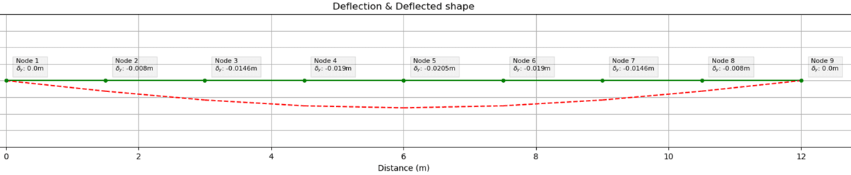
Fig 8. SLS deflection.
Note that for this worked example, the applied load at the serviceability limit state is . The maximum observed deflection, .
For a typical steel beam without any special restrictions on deflection, the limiting deflection under total load will often be taken as L/360.
Therefore
Since we can accept this deflection.
6.0 Initial sizing of plate girders
Up to this point in the tutorial, we’ve focused on the detailed steps required to complete a plate girder design compliant with Eurocode 3. However, an Engineer will often need to make a quick assessment of the required size of a plate girder.
The following 'rules of thumb' are useful to aid the initial sizing of I-section plate girders. Remember, these rules of thumb do not constitute a full design!
6.1 Span to depth
For most I-section plate girders, the following span-to-depth ratio will be useful to calculate an initial section depth.
6.2 Flange thickness ()
We can estimate the necessary flange area () by considering the lever arm of the section which we estimated in 6.1.
6.3 Flange width ()
To ensure that the flanges of the I-section girder are not class 4, the following approximation is commonly used.
where,
Therefore,
Rearranging,
6.4 Web width ()
The web width is typically approximated based on the flange width.
7.0 Wrapping up
I hope you found this tutorial on the design of plate girders to Eurocode 3 helpful. It is intended to give you the skills and confidence to use Eurocode 3 Part 1-1 and Part 1-5 to design I-section plate girders.
You should now have a good understanding of the different design checks which we conduct and the reasons why we conduct them. Eurocode 3 Part 1-5 is an incredibly powerful and flexible design code and we have really only touched the surface in this tutorial.
That's it for this four-part series on the design of steel elements to Eurocode 3. Watch out for new design-focused tutorials coming soon.

Featured Tutorials and Guides
If you found this tutorial helpful, you might enjoy some of these other tutorials.

A primer on the form and behaviour of gridshell structures
The evolution of gridshells and techniques for form finding and analysis

Dr Seán Carroll

How to Apply the Virtual Work Method to Trusses
Apply the Principle of Virtual Work to determine truss deflections
Dr Seán Carroll

How to Calculate Beam Deflection
How to calculate beam deflection from first principles, with calculation examples
Dr Seán Carroll