Yielding, Plastic Deformation and Moment Redistribution in Beams (2/2)
![[object Object]](/_next/image?url=%2Fimages%2Fauthors%2Fsean_carroll.png&w=256&q=75)
In the previous post in this series we introduced the idea of elastoplastic bending. We showed how the normal/bending stress distribution transitioned from linearly elastic to fully plastic. We saw that a fully plastic cross-section behaved just like a hinge allowing free rotation if further loading was applied to the structure. We finished that post with the clear understanding that a cross-section has additional plastic moment capacity (ductile materials only!)
In this tutorial, we’re going to work out exactly how to determine the plastic moment capacity of a cross section. We’ll also explore the concept of moment redistribution with an illustrative example. By the end of this post you’ll be able to calculate the plastic moment capacity of any cross-section and understand in detail how moment redistribution occurs in a structure.
Plastic Moment Capacity and the Shape Factor
Once we’ve established the fact that a cross-section can go beyond its elastic limit and sustain further loading after it has begun to yield, the obvious question is how much more load can it withstand? We can start by considering a cross-section which has reached its plastic limit.
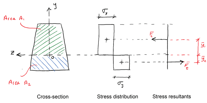
We know that to satisfy equilibrium, the total force acting on the cross-section must be zero, therefore,
We know force is simply the product of stress and area (over which the stress acts), so,
From this we can conclude that when a cross-section has fully yielded, the neutral axis divides the cross-section into two equal areas. So, if the z-axis is not an axis of symmetry (and it’s not in the case of the trapezoidal cross-section shown above), the neutral axis under plastic conditions will be in a different location to the neutral axis under elastic conditions. We can now state an expression for the plastic moment as,
Now since,
We can state that the plastic moment is,
We now define the plastic section modulus as,
And we can state the plastic moment as,
It should be noted that the plastic modulus is purely a function of the cross-section shape.
Shape Factor
We know from basic beam bending theory that the elastic moment is given by,
and that the elastic modulus is given by,
Now we define the ratio of plastic moment, to yield moment as the shape factor, and note that this ratio is ultimately a function of the cross-section shape,
💡 The shape factor is a measure of how much reserve strength is in the cross-section after yielding begins.
The shape factor is a helpful indicator of how much more loading can be sustained after yielding but before a plastic hinge is formed. Remember, it is simply a function of the shape of the cross-section and is independent of the material properties of the cross-section.
Calculating the Plastic Moment Capacity
Now we’ve covered all of the theory, let’s actually calculate the plastic moment capacity and shape factor of a cross-section. To make things a little more interesting we’ll consider a compound cross-section consisting of an I-beam with a steel plate welded to the bottom flange. We’ll assume a steel yield stress of .
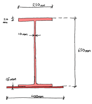
You can watch me walk through the full solution to this question in the video below (the thought of typesetting the full thing in this post was too much to take!) But the outline steps are as follows:
- We need to calculate the second moment of area using the parallel axis theorem. But as this is a compound section and not symmetrical about the neutral axis, we’ll need to first locate the neutral axis, by taking area moments about an arbitrary axis.
- Armed with the second moment of area and neutral axis location, we can plug these into the engineer’s bending equation (equation 8 above) to determine the moment required to cause yielding, .
- Then we can move on and determine the location of the equal area axis. Remember the neutral axis becomes an equal area axis (and may shift location) in the fully plastic condition.
- Once we have the equal area axis, we can work out the plastic moment capacity and apply equation (10) to determine the shape factor.
It’s worth you trying to solve this yourself first before watching me solve it in the video below.
Plastic Hinges in Beams and Moment Redistribution
Now we’re going to expand our study of elastoplastic behaviour beyond the cross-section to look at hinge formation in a beam. Consider the simply supported beam below subject to an increasing point load at mid-span. By examining the bending moment diagram, we can map out and visualise the formation of a plastic hinge under the point load.
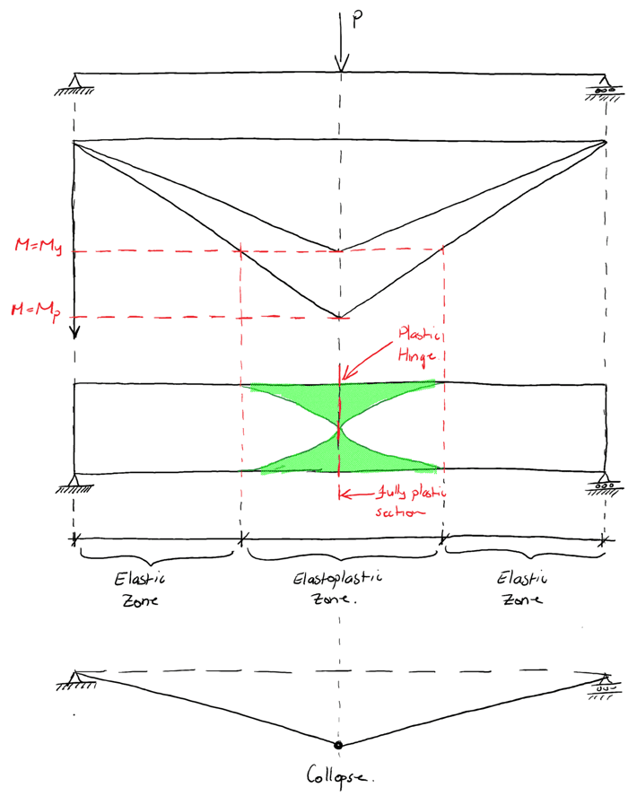
We can clearly see how the bending moment diagram can be used to identify the extent of the elastoplastc region in the beam. As we now know, once the entire section becomes plastic (as indicated at the mid-span in the beam above) a plastic hinge forms.
Now we’ll consider how hinge formation allows moment to be redistributed in a statically indeterminate structure. We demonstrate the fundamentals of this behaviour by considering a simple (indeterminate) propped cantilever.
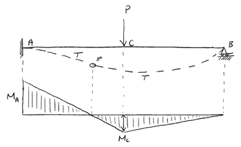
It can be shown that the bending moments at A and C are:
We’re going to set ourselves a simple task; to determine the value of the applied load, at which the structure collapses. In doing so we’ll need to take account of plastic hinge formation and moment redistribution.
We can start by stating some basic assumptions:
- Let the span
- Let the yield moment
- Let the plastic moment
Let’s also assume the the beam must accommodate an applied working load .
Analysis for P=25 kN
Under normal working conditions, the moments at A and C are:
Both moments are less than the yield moment therefore the beam is safe under working conditions. So let’s push things further – remember we want to know the load at which the beam collapses.
Analysis for P=32 kN
Again determining the moments in the structure:
Therefore the cross-section at location A has reached its yield limit; i.e. the extreme fibres in the cross-section at this location have reached their yield stress. In a linearly elastic analysis we would call this the maximum allowable load and end things here. But as we know, this beam can take more, so let’s push things further still.
Analysis for P=40 kN
In this case, the moments are:
At this point, a plastic hinge has formed at A. Any further loading will cause free rotation to occur at this location.
At C, the section has exceeded its elastic limit and yielding has started. At location C the section is undergoing elastoplastic bending.
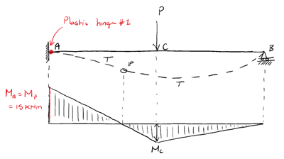
It’s important to remember that the structure started out as indeterminate to 1 degree i.e. it had one redundancy. It has just lost this redundancy with the formation of a plastic hinge at A. The structure will not collapse yet, but if one more hinge forms, the structure will become a mechanism and will collapse.
Analysis for P=45 kN (Moment Redistribution!)
At this load, the moment at A remains 15 kNm. Remember, the section can’t withstand any more moment once a hinge has formed. Any further loading after hinge formation simply causes rotation about the plastic hinge.
So if any additional load is applied, we must have moment redistribution in the beam. This is inevitable; the load is continuing to increase, but a hinge has formed at A allowing the section to rotate at that location. If the structure is to avoid collapse, the increased moment within the structure must be redistributed from the support at A and into the span, further increasing the moment at C.
The formation of a plastic hinge at A means that the structure now behaves as a simply supported beam. In other words, all of the load applied between P=40 kN and P=45 kN is resisted by the structure as if it were a simply supported beam.
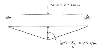
Now determining the moment at C:
We can see that at this value of applied load, a hinge will form at C. The structure now becomes a mechanism and collapses.
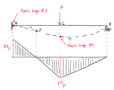
The load at which collapse occurs is 45 kN while the load at which yielding first occurs is 32 kN. So this structure could withstand approximately 40% more load before collapse than an elastic analysis would suggest.
This ability to safely sustain loading after plastic hinge formation is often utilised in structural design. Large span steel portal frames are often designed to develop plastic hinges. Care must obviously be taken to ensure sufficient redundancy remains to ensure collapse does not occur.
Plastic Collapse Analysis
We can define a load factor as the collapse load for mechanism , divided by the structures’ working load,
For a structure with multiple collapse mechanisms, the collapse load factor is the smallest value of the load factor – the load factor at which the structure will collapse. For our example above, the collapse load factor is,
We might explore plastic collapse analysis in another tutorial series. But for now you should have a good understanding of the material and cross-section behaviour that leads to collapse of ductile structures and the additional capacity that exists, after material yielding but before plastic hinge formation.
In case you missed it, the first tutorial in this 2 part series can be found here.
Dr Seán Carroll's latest courses.


Featured Tutorials and Guides
If you found this tutorial helpful, you might enjoy some of these other tutorials.
Code, Context, and Calculation - A Modern Framework for Engineering
Building reliable and auditable systems with Python and AI

James O'Reilly
Column Buckling Equations
Determine column buckling equations for axially loaded column with different end conditions

Dr Seán Carroll


